Eureka AIR delivers breakthrough ideas for toughest innovation challenges, trusted by R&D personnel around the world.

Single-lamp visible light duplex communication system, and uplink and downlink time division method thereof

A duplex communication and visible light technology, applied in the field of visible light communication, can solve the problems of visible light eye irritation, non-compliance with the design concept of green environmental protection, increased power consumption and cost of equipment, etc., to solve the problem of tight spectrum resources and good ergonomic design , the effect of saving light source

Inactive Publication Date: 2017-03-22
HEBEI NORMAL UNIV
View PDF7 Cites 2 Cited by
  • Summary
  • Abstract
  • Description
  • Claims
  • Application Information

AI Technical Summary

Problems solved by technology

However, for the lower computer (client receiver), when it has the function of sending and receiving at the same time, the existing system must install a transmission system equivalent to the upper computer, that is to say, ordinary mobile phones or tablet computers and other terminal Internet access devices, if If you use visible light access technology, you must install a visible light transmitter, which will bring a serious problem to users, that is, the stimulation of visible light to human eyes
At the same time, if the client's Internet access device transmits information by lighting LED lights or other light sources, it will add additional power consumption and cost to the device, which does not conform to the design concept of green environmental protection

Method used


Image

  • Single-lamp visible light duplex communication system, and uplink and downlink time division method thereof
  • Single-lamp visible light duplex communication system, and uplink and downlink time division method thereof
  • Single-lamp visible light duplex communication system, and uplink and downlink time division method thereof

Examples


Embodiment Construction

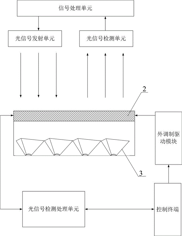
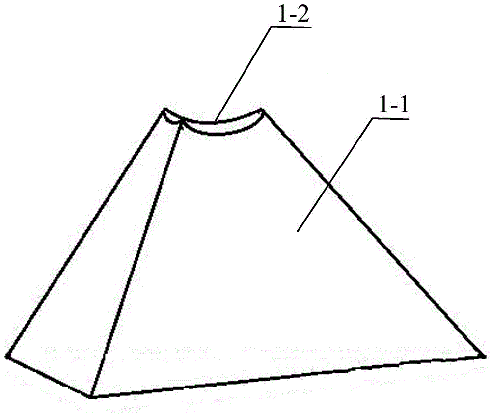
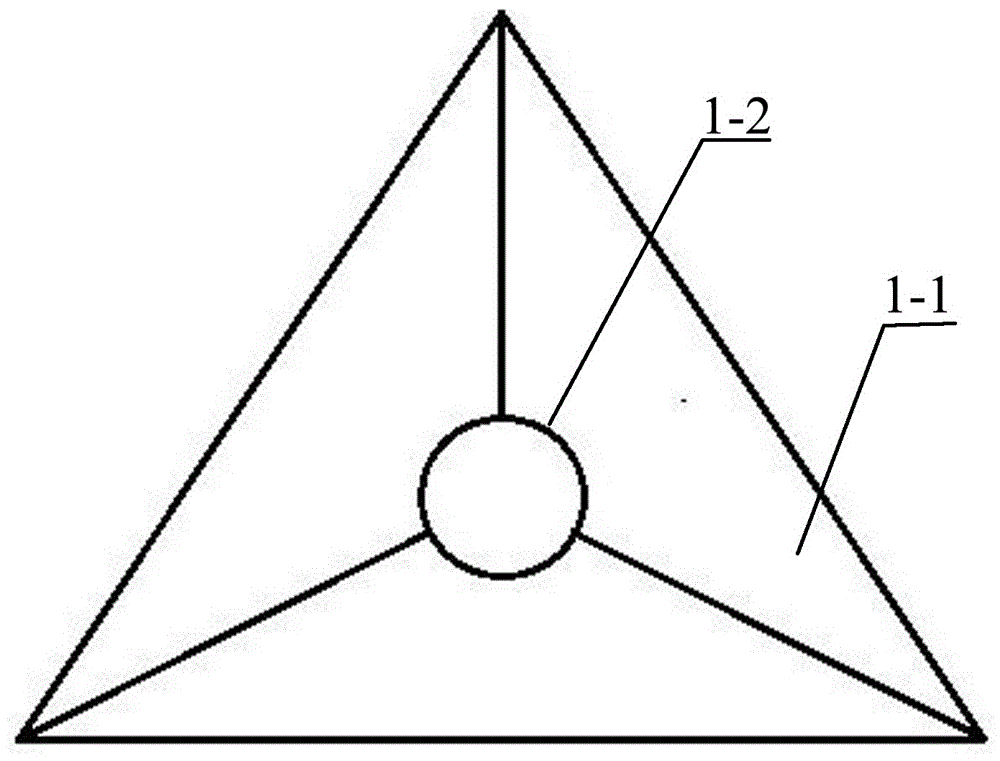
[0023] Depend on Figure 1-6 It can be known from the illustrated embodiment that the single-lamp visible light duplex communication system is characterized in that it includes a host computer and a slave computer; the host computer includes a first signal processing unit, a first optical signal transmitting unit, and a first optical signal detection unit The lower computer includes a single-chip external modulator 2, a reflective prism group 3, a second optical signal detection unit 4, a second signal processing unit, an external modulation drive module and a control terminal; the single-chip external modulator 2, reflective The prism group 3 and the second optical signal detection unit 4 are respectively fixedly arranged on the lower equipment bracket 5, and the single-chip external modulator 2 is arranged above the reflective prism group 3; the input terminal of the first optical signal transmitting unit is connected to the second The corresponding output terminal of a sign...


PUM


Abstract

The invention discloses a single-lamp visible light duplex communication system, and an uplink and downlink time division method thereof. The communication system comprises an upper computer and a lower computer; the upper computer comprises a first signal processing unit, a first optical signal transmitting unit and a first optical signal detection unit; and the lower computer comprises a single-wafer type external modulator, a reflective prism set, a second optical signal detection unit, a second signal processing unit, an external modulation driving module and a control terminal. The method for realizing uplink and downlink time division comprises the following steps of: setting uplink data and downlink data, and, according to time division, distinguishing an uplink data channel from a downlink data channel, and performing self-adaptive distribution. By means of the single-lamp visible light duplex communication system, and the uplink and downlink time division method thereof disclosed by the invention, the light source of the lower computer can be saved; light cannot irritate eyes of users; the data transmission rate is high; and the scientific research value, the economic benefit and the social benefit are relatively high.

Description

technical field [0001] The invention belongs to the technical field of visible light communication, and in particular relates to a single-lamp visible light duplex communication system and an uplink and downlink time division method thereof. Background technique [0002] Visible light communication technology is an emerging broadband access technology. It mainly uses high-power white light LED as the light source, and loads the communication signal to the light-emitting white light LED, so that the change of the signal becomes the change of light and is emitted. In the past, the visible light communication duplex system required two sets of light sources for the transceiver system. The upper computer had a light source as the transmitter light source, and a photodetector as the receiver optical signal detection device; the lower computer had a light source as the transmitter light source, and a photodetector As a receiver optical signal detection device. There is a common ...

Claims


Application Information

Patent Timeline
IPC IPC(8): H04B10/116H04B10/50H04L5/14
CPCH04B10/116H04B10/501H04L5/14
Inventor 赵华陈嘉兴刘豪锋吕清黄战平张书景马路娟刘亚川刘静静
Owner HEBEI NORMAL UNIV
Why Eureka
Eureka Blog
Learn More