
Marine diesel engine tail gas afterheat temperature difference energy utilization device

A technology for marine diesel engine and temperature difference energy, which is applied to exhaust devices, mufflers, electrical components, etc., can solve problems such as affecting work efficiency, damage to power generation sheets, waste of energy, etc., and achieve comprehensive and efficient utilization, comprehensive and efficient cold energy and heat energy. Effect

Active Publication Date: 2017-03-29
WEIHAI OCEAN VOCATIONAL COLLEGE
View PDF6 Cites 4 Cited by
  • Summary
  • Abstract
  • Description
  • Claims
  • Application Information

AI Technical Summary

Problems solved by technology

The temperature of seawater is usually lower than the ambient temperature. The seawater used to vaporize LNG and other substances on ships has a lot of cold energy. If it is not utilized, a lot of energy will be wasted
[0003] The semiconductor thermoelectric power generation chip can make good use of the temperature difference to generate electricity, but the power generation chip has a certain working range. If the temperature is too high or too low, it will affect the working efficiency and even damage the power generation chip. physically

Method used


Image

  • Marine diesel engine tail gas afterheat temperature difference energy utilization device
  • Marine diesel engine tail gas afterheat temperature difference energy utilization device
  • Marine diesel engine tail gas afterheat temperature difference energy utilization device

Examples


Embodiment Construction

[0015] The following are specific embodiments of the present invention, and further describe the technical solution of the present invention in conjunction with the accompanying drawings, but the present invention is not limited to these embodiments.

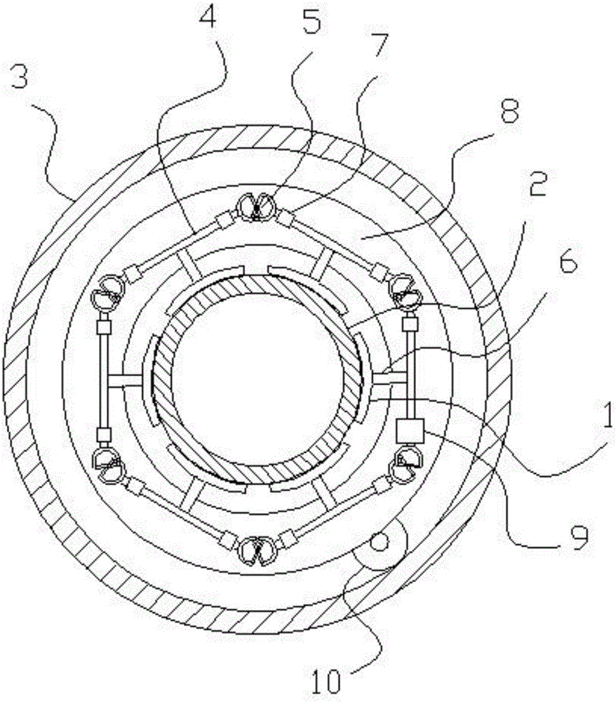
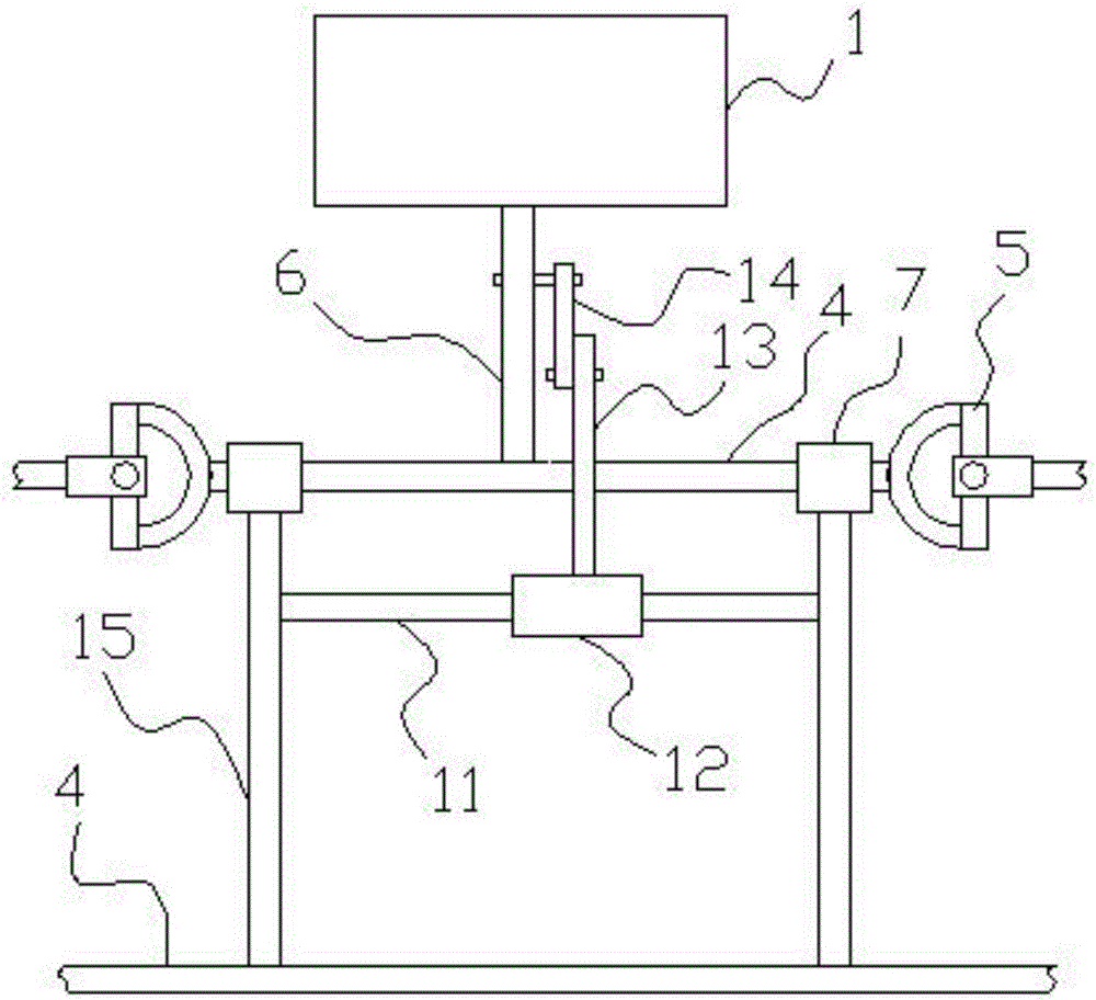
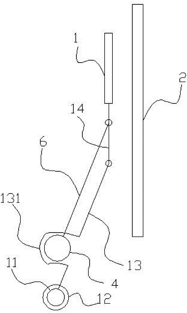
[0016] Such as figure 1 As shown, a marine diesel engine exhaust waste heat temperature difference energy utilization device includes a semiconductor thermoelectric power generation chip 1 and a coaxial cooling sleeve 3 that is placed outside the engine exhaust discharge pipe 2 . A cooling water pipe is coiled outside the cooling sleeve for connecting the water of the cooling source. A frame body is arranged between the exhaust gas discharge pipe and the cooling sleeve, and the frame body is a regular hexagon frame body formed by connecting the rotating shafts 4 end to end. The crank rod 6 perpendicular to the rotating shaft. Each rotating shaft is provided with a bearing 7, and an annular turntable is arranged between the tai...


PUM


Abstract

The invention provides a marine diesel engine tail gas afterheat temperature difference energy utilization device, which belongs to the technical field of afterheat energy utilization, and relates to a tail gas afterheat temperature difference energy utilization device. The marine diesel engine tail gas afterheat temperature difference energy utilization device solves the problems that in the prior art, the tail gas temperature is higher, and a great amount of heat energy is not utilized and is wasted. The marine diesel engine tail gas afterheat temperature difference energy utilization device comprises a semiconductor temperature difference power generating sheet, and is characterized by also comprising a cooling sleeve, wherein the cooling sleeve coaxially sleeves an engine tail gas exhaust pipe; a cooling water pipe is coiled outside the cooling sleeve; a framework body is arranged between the tail gas exhaust pipe and the cooling sleeve; the framework body is an orthohexagonal framework body formed by connecting rotating shafts end to end; the rotating shafts are mutually connected through a universal shaft coupler; a crank rod vertical to the rotating shaft is arranged on each rotating shaft; the end part of each crank rod is provided with the semiconductor temperature difference power generating sheet; a bearing is arranged on each rotating shaft. The marine diesel engine tail gas afterheat temperature difference energy utilization device has the advantages that the work temperature of refrigeration sheets is regulated, and the cold energy and the heat energy are integrally utilized.

Description

technical field [0001] The invention belongs to the technical field of waste heat energy utilization, and relates to an exhaust waste heat temperature difference energy utilization device, in particular to a ship diesel engine exhaust waste heat temperature difference energy utilization device. Background technique [0002] The power of marine diesel engines is high, and a large amount of exhaust gas must be emitted during operation. These exhaust gases have a high temperature and contain a large amount of heat energy that is useless and discharged in vain. The temperature of seawater is usually lower than the ambient temperature. The seawater used to vaporize LNG and other substances on ships has a lot of cold energy. If it is not utilized, a lot of energy will be wasted. [0003] The semiconductor thermoelectric power generation chip can make good use of the temperature difference to generate electricity, but the power generation chip has a certain working range. If the te...

Claims


Application Information

Patent Timeline
IPC IPC(8): F01N5/02H02N11/00
CPCF01N5/025H02N11/002Y02T10/12
Inventor 耿保阳滕强张启友李晓房良宋倩连建鲁
Owner WEIHAI OCEAN VOCATIONAL COLLEGE
Learn More