Wind power plant and power-to-gas plant and station collaborative location planning method

A technology for converting electricity to gas and wind farms, which is used in instruments, data processing applications, information technology support systems, etc.

Inactive Publication Date: 2017-03-29
国网浙江省电力公司电动汽车服务分公司 +1
View PDF0 Cites 12 Cited by
  • Summary
  • Abstract
  • Description
  • Claims
  • Application Information

AI Technical Summary

Problems solved by technology

[0004] The purpose of the present invention is to address the deficiencies in the prior art, to provide a collaborative site selection planning method for wind farms and powe

Method used


Image

  • Wind power plant and power-to-gas plant and station collaborative location planning method
  • Wind power plant and power-to-gas plant and station collaborative location planning method
  • Wind power plant and power-to-gas plant and station collaborative location planning method

Examples


Embodiment

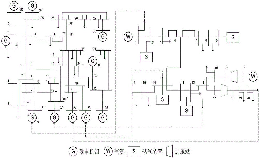
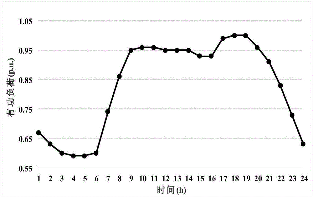
[0165] Parameter setting: based on the IEEE 39-node power system and the Belgian 20-node natural gas system, figure 1 The electrical-pneumatic interconnection system shown is an example to test the proposed method. In the IEEE 39-node system, the units located at nodes 30, 35, 36, 37, 38, and 39 are conventional units, and the units located at nodes 31 to 34 are gas-fired units. The unit and load parameters of the 39-node system have been modified, as shown in Table 1, Table 2 and figure 2 shown. It is assumed that nodes 9 and 13 in the power system are rich in wind energy resources, and the power system and natural gas system are coupled near these two nodes. After analysis, the test system has the following two location planning schemes:

[0166]Option 1: Build a 400MW wind farm at node 9 of the power system; consider building a 20MW PtG power station, which will be connected to node 5 of the natural gas system after completion.

[0167] Option 2: Build a 400MW wind far...


PUM


Abstract

The invention discloses a wind power plant and power-to-gas plant and station collaborative location planning method. The method comprises the following steps: 1) establishing a mathematic model of a power-to-gas plant and station; 2) with historical wind speed time series being an original scene, carrying out clustering analysis on a large number of historical data by utilizing a density-based clustering algorithm to obtain a reduced wind power plant output scene; 3) according to the mathematic model obtained in the step 1) and the wind power plant output scene obtained in the step 2), and with net investment income maximization being an optimization objective, establishing a collaborative location planning mathematical model based on scene analysis; and 4) according to the steps 1)-3), solving the constructed collaborative location planning mathematical model of the wind power plant and the power-to-gas plant through an AMPL/BONMIN solver to obtain a planning result. The collaborative location planning method can take technical features of operation of the power-to-gas plant and station into consideration, can evaluate and analyze economy of the planning scheme and can effectively reduce system wind abandoning quantity.

Description

technical field [0001] The invention relates to the field of electric power system planning, in particular to a collaborative site selection planning method for wind farms and power-to-gas plants. Background technique [0002] In recent years, the environmental pressure brought by energy consumption has gradually increased, and the focus of energy development and utilization has gradually shifted to wind energy and other renewable energy sources. However, in the transformation and utilization of renewable energy, the phenomena of abandoning wind and solar still exist. In order to improve energy conversion and utilization efficiency, the coupling between different energy systems has gradually attracted attention. The traditional power system is connected with the natural gas system through the gas-fired unit, but the power-to-gas (PtG) technology that has emerged in recent years makes the closed-loop coupling between the two possible. PtG technology can convert electrical e...

Claims


Application Information

Patent Timeline
IPC IPC(8): G06Q50/06
CPCG06Q50/06Y04S10/50
Inventor 俞哲人王芃刘伟佳文福拴毛建伟李波李梁袁军吕浩华
Owner 国网浙江省电力公司电动汽车服务分公司
Why Eureka
Try Eureka