
Etching method for laminated inorganic membrane

An inorganic film and etching technology, which is applied in the field of etching of laminated inorganic films, can solve problems such as uneven etching thickness, and achieve the effect of improving uniformity

Inactive Publication Date: 2017-03-29
WUHAN CHINA STAR OPTOELECTRONICS TECH CO LTD
View PDF3 Cites 2 Cited by
  • Summary
  • Abstract
  • Description
  • Claims
  • Application Information

AI Technical Summary

Problems solved by technology

[0004] However, due to the limitations of existing technologies, in the actual production process, such as figure 1 As shown, different areas on the same substrate pass through the photoresist layer 109 to dry-etch the passivation layer 107 of the laminated inorganic film at different rates, resulting in uneven etching thickness; figure 1 The middle A region corresponds to the region with a slower dry etching rate, and at the end of the dry etching, the etching depth of the passivation layer 107 is not enough to form a via hole in the passivation layer 107; figure 1 The middle B region corresponds to the region with a moderate dry etching rate, and at the end of the dry etching, the passivation layer 107 is etched to an appropriate depth and just forms a via hole on the passivation layer 107; figure 1 The middle C area corresponds to the area with a faster dry etching rate. At the end of the dry etching, not only the via hole is formed on the passivation layer 107, but also the gate insulating layer 103 of the silicon nitride material of the lower layer is etched correspondingly, so it corresponds to The above-mentioned uneven dry etching situation, especially for the thicker laminated inorganic film, needs to form a deeper via hole with a depth greater than 1 μm on it, the above-mentioned uneven etching situation is more obvious, therefore, it is necessary to solve the current problem. Some methods of etching laminated inorganic films have been improved

Method used


Image

  • Etching method for laminated inorganic membrane
  • Etching method for laminated inorganic membrane
  • Etching method for laminated inorganic membrane

Examples


Embodiment Construction

[0025] In order to further illustrate the technical means adopted by the present invention and its effects, the following describes in detail in conjunction with preferred embodiments of the present invention and accompanying drawings.

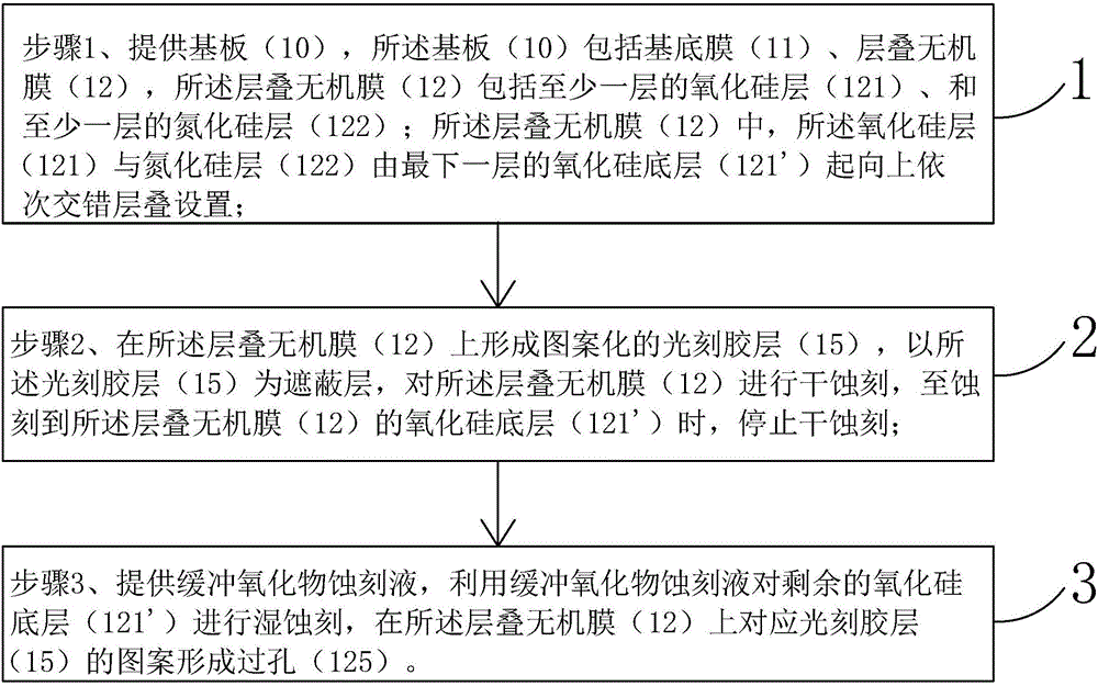
[0026] see figure 2 , the invention provides a method for etching a laminated inorganic film, comprising the following steps:

[0027] Step 1. Provide a substrate 10, the substrate 10 includes a base film 11, and a laminated inorganic film 12 disposed on the base film 11, the laminated inorganic film 12 includes at least one silicon oxide layer 121, and at least one layer of silicon nitride layer 122; in the stacked inorganic film 12, the silicon oxide layer 121 and the silicon nitride layer 122 are stacked upwards in sequence from the bottom silicon oxide layer 121, and the bottom layer The silicon oxide layer 121 is a silicon oxide bottom layer 121'.

[0028] Step 2, see image 3 and Figure 4 , forming a patterned photoresist layer 15 ...


PUM


Abstract

The invention provides an etching method for a laminated inorganic membrane, which combines dry etching and wet etching for etching of the laminated inorganic membrane. The method comprises the following steps: a patterned photoresist layer is firstly formed on the laminated inorganic membrane, the dry etching of the laminated inorganic membrane is carried out in a manner that the photoresist layer serves as a shielding layer, and the dry etching is stopped when a silicon oxide bottom layer at the bottommost layer of the laminated inorganic membrane is to be etched; and the wet etching is then carried out on the remaining silicon oxide bottom layer through a buffered oxide etch (BOE), so that via holes are formed in the laminated inorganic membrane corresponding to patterns of the photoresist layer. The method provided by the invention has the advantages that the uniformity of etching effects for various areas of a same substrate can be improved, so that the phenomenon in the prior art that a lower membrane is etched due to non-uniform etching of the various areas when the via holes, especially deep via holes, are formed in the laminated inorganic membrane is prevented.

Description

technical field [0001] The invention relates to the field of display technology, in particular to an etching method for stacking inorganic films. Background technique [0002] Thin Film Transistor (TFT) is the main driving element in current Liquid Crystal Display (LCD) and Active Matrix Organic Light-Emitting Diode (AMOLED). It is related to the display performance of the flat panel display device. [0003] Both LCD and AMOLED include a TFT array substrate. In the manufacturing process of the TFT array substrate, an etching gas is used, an organic film such as photoresist is used as a mask, and silicon oxide (SiO 2 ) film and silicon nitride (SiN x ) film laminated film etch dry etching process, wherein, the etching gas to the silicon oxide film and silicon nitride film relative to the selective etching of photoresist is high, that is, the silicon oxide film and silicon nitride film have selective etching properties, pattern-shaped via holes can be formed in a laminated...

Claims


Application Information

Patent Timeline
Patent Type & Authority Applications(China)
IPC IPC(8): H01L21/77H01L21/311H01L27/12
CPCH01L27/1259H01L21/31111H01L21/31144H01L27/1296
Inventor 金映秀
Owner WUHAN CHINA STAR OPTOELECTRONICS TECH CO LTD
Learn More