Motor and motor protection method

An isolation protection, circuit technology, applied in emergency protection circuit devices, electrical components and other directions, can solve the problems of power tube breakdown, DC motor winding insulation damage, etc., to achieve the effect of rapid braking

Inactive Publication Date: 2017-03-29
QINGDAO HAIER TECH
View PDF5 Cites 14 Cited by
  • Summary
  • Abstract
  • Description
  • Claims
  • Application Information

AI Technical Summary

Problems solved by technology

Even cause the insulation damage of the inner win...

Method used


Image

  • Motor and motor protection method
  • Motor and motor protection method
  • Motor and motor protection method

Examples


no. 1 example

[0051] In the first embodiment of the present invention, a motor protection method, such as Figure 5 shown, including the following specific steps:

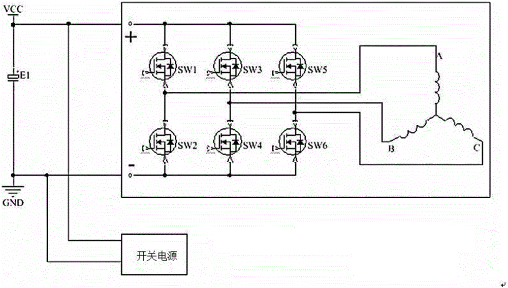
[0052] Step S101, setting a discharge brake circuit and a detection control circuit between the motor switching power supply and the motor.

[0053] Wherein, the bleed brake circuit includes a bleed resistor and a controlled switch;

[0054] The discharge brake circuit is connected in parallel between the positive pole and the negative pole of the motor power supply end;

[0055] The power detection end of the detection control circuit is connected with the switching power supply of the motor, and the control signal output end of the detection control circuit is connected with the controlled switch of the discharge brake circuit.

[0056] For example: the discharge brake circuit is connected in parallel between the positive pole and the negative pole of the motor power supply end; the discharge brake circuit includes: a series...

no. 2 example

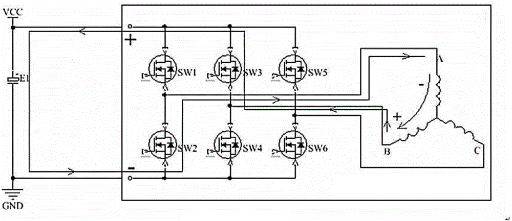
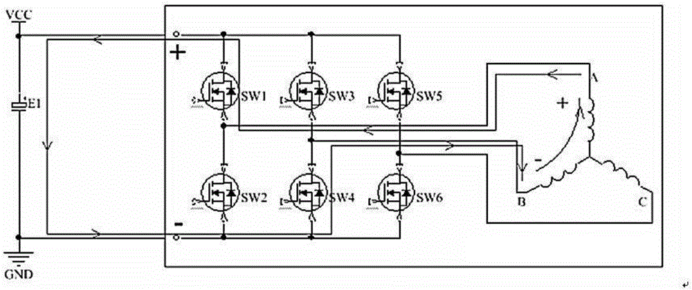
[0075] In the second embodiment of the present invention, a motor protection method, such as Image 6 with Figure 7 As shown, the method in this embodiment includes the following specific steps:

[0076] Step S201, setting a discharge brake circuit and a detection control circuit between the motor switching power supply and the motor.

[0077] Wherein, the bleed brake circuit includes a bleed resistor and a controlled switch;

[0078] The discharge brake circuit is connected in parallel between the positive pole and the negative pole of the motor power supply end;

[0079] The power detection end of the detection control circuit is connected with the switching power supply of the motor, and the control signal output end of the detection control circuit is connected with the controlled switch of the discharge brake circuit.

[0080] For example: if Image 6 As shown, the bleed brake circuit is connected in parallel between the positive pole and the negative pole of the mot...

no. 3 example

[0110] The third embodiment of the present invention, this embodiment introduces a motor, such as Figure 8 shown, including the following components:

[0111] Motor switching power supply, discharge brake circuit and detection control circuit;

[0112] The discharge brake circuit is connected in parallel between the positive pole and the negative pole of the motor power supply end;

[0113] The detection control circuit is respectively connected with the motor switching power supply and the discharge braking circuit;

[0114] The detection control circuit is used to control the discharge brake circuit based on the judgment result of whether the motor is powered off;

[0115] The discharge brake circuit is used to discharge the energy of the self-induced electromotive force and the counter electromotive force of the motor under the control of the detection control circuit.

[0116] Wherein, the bleed brake circuit includes a bleed resistor RL and a controlled switch K1;

[0...


PUM


Abstract

The invention proposes a motor and a motor protection method. The method comprises the steps of arranging a discharging braking circuit and a detection control circuit between a motor switch power supply and the motor; and monitoring whether the motor is powered off or not by the detection control circuit, if yes, controlling the discharging braking circuit to discharge energy of a self-induced electromotive force and a counter electromotive force of the motor. By the motor and the motor protection method, an electrolytic capacitor at a front end can be prevented from being charged by the self-induced electromotive force and the counter electromotive force which are generated during stopping rotation of a DC motor, the system switch power supply is prevented from being started again after stopping working, the self-induced electromotive force and the counter electromotive force which are generated during stopping rotation of the motor can be converted to heat energy and are rapidly released, and rapid braking of a draught fan is achieved.

Description

technical field [0001] The invention relates to the technical field of motors, in particular to a motor and a motor protection method. Background technique [0002] At present, when the brushless DC motor is directly powered off, the self-induced electromotive force of the brushless DC motor and the back electromotive force generated by the fan blade of the brushless DC motor during the rotation process after power failure will generate high voltage, and the high voltage will Charging other peripheral circuits of the brushless DC motor will cause the switching power supply of the brushless DC motor system to restart, and even damage the internal components of the DC motor. [0003] For example: if figure 1 As shown, the brushless DC motor switching power supply circuit transmits the high-voltage DC power supply 310V generated by the AC mains 220V after being rectified by the rectifier to the brushless DC motor, which is used as the power input of the brushless DC fan and al...

Claims


Application Information

Patent Timeline
IPC IPC(8): H02H7/08
CPCH02H7/0811
Inventor 关宏星
Owner QINGDAO HAIER TECH
Why Eureka
Try Eureka