Power distribution network coordinated control method

A technology of coordinated control and distribution network, applied in the direction of photovoltaic power generation, electrical components, circuit devices, etc., can solve the problems of inability to apply the distribution network, unable to ensure the safe and economic operation of the distribution network, etc., to ensure safe and economic operation, optimization running effect

Active Publication Date: 2017-03-29
ELECTRIC POWER RESEARCH INSTITUTE, CHINA SOUTHERN POWER GRID CO LTD +1
View PDF3 Cites 13 Cited by
  • Summary
  • Abstract
  • Description
  • Claims
  • Application Information

AI Technical Summary

Problems solved by technology

Therefore, the traditional power system reactive power optimization method cannot be applied to the optimization process of the distribution network containing photovoltaic systems (that is, including photovoltaic systems and energy storage devices), so that the safe and economical operation of the distribution network cannot be guaranteed.

Method used


Image

  • Power distribution network coordinated control method
  • Power distribution network coordinated control method
  • Power distribution network coordinated control method

Examples


Embodiment 1

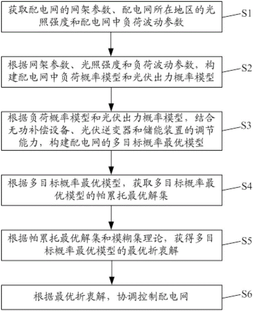
[0021] Embodiments of the present invention provide a method for coordinated control of a distribution network, such as figure 1 As shown, the distribution network coordination control method includes:

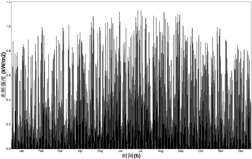
[0022] Step S1, obtaining grid parameters of the distribution network, light intensity in the area where the distribution network is located, and load fluctuation parameters in the distribution network.

[0023] Exemplarily, the grid parameters of the above-mentioned distribution network may include network topology, line parameters, distribution transformer parameters, load parameters, reactive power compensation equipment parameters, optical storage system parameters, and the like.

[0024] Specifically, the network topology refers to the connection mode between lines and lines and between lines and distribution transformers in the distribution network; line parameters include the length L of each line in the distribution network i , the unit resistance r of each line 0i ,...

Embodiment 2

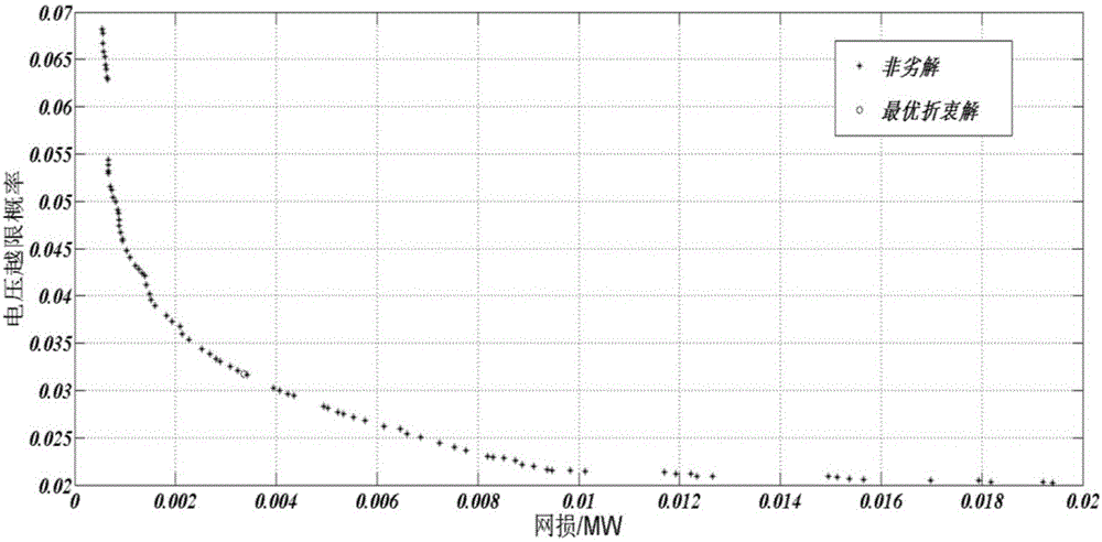
[0072] The embodiment of the present invention will give a specific application example of using the distribution network coordinated control method in the first embodiment to coordinately control the distribution network:

[0073] The IEEE-34 node standard test system is selected to simulate the above-mentioned distribution network with optical storage system, the system reference capacity is 1MVA, and the reference voltage is 24.9kV (1.030p.u.). The specific values ​​of active load and reactive load of each node in the test system are shown in Table 1, in which the active load and reactive load are per unit value (unit is p.u.). Among them, parallel capacitor banks are connected to the 4th node, 10th node, 13th node, 23rd node and 28th node, and the number of capacitor banks connected to the 5 nodes is 4 groups. The capacitor capacity is 10kvar; it is connected to the optical storage system at the 34th node, wherein the maximum charging power of the energy storage device is ...


PUM


Abstract

The invention discloses a power distribution network coordinated control method and belongs to the power distribution network control technical field. With the method adopted, the technical problem that a traditional power system reactive power optimization method cannot be applied to the optimization process of an optical storage system-containing power distribution network can be solved. The method of the invention includes the following steps that: a load probability model and a photovoltaic output probability model in a power distribution network are constructed according to network framework parameters, illumination intensity and load fluctuation parameters; a multi-objective probability optimal model of the distribution network is constructed according to the load probability model and the photovoltaic output probability model and based on the adjustment capacity of a reactive power compensation device, a photovoltaic inverter and an energy storage device; the Pareto optimal solution set of the multi-objective probability optimal model is obtained according to the multi-objective probability optimal model; the optimal compromise solution of the multi-objective probability optimal model is obtained according to the Pareto optimal solution set and the fuzzy set theory; and the power distribution network is controlled in a coordinated manner according to the optimal compromise solution. The power distribution network coordinated control method of the present invention is applied to the coordinated control of power distribution networks.

Description

technical field [0001] The invention relates to the technical field of distribution network control, in particular to a method for coordinated control of a distribution network. Background technique [0002] The traditional power system reactive power optimization is a control method used to ensure the safe and economical operation of the system. In the case of satisfying each constraint condition, the optimization goal of minimizing the active power loss of the entire power system is achieved. [0003] However, with the rapid development of power systems and solar photovoltaic power generation, a large number of photovoltaic power sources are connected to the grid. On the one hand, the output of photovoltaic power sources will cause grid voltage fluctuations and increase the risk of voltage over-limits. On the other hand, photovoltaic power sources will change. The original power flow characteristics of the power grid affect the economy of the power grid operation. In add...

Claims


Application Information

Patent Timeline
Patent Type & Authority Applications(China)
IPC IPC(8): H02J3/18H02J3/46
CPCH02J3/1821H02J3/46Y02E10/56Y02E40/30
Inventor 周保荣刘斯亮金小明羿应棋张勇军李鸿鑫李峰赵文猛
Owner ELECTRIC POWER RESEARCH INSTITUTE, CHINA SOUTHERN POWER GRID CO LTD
Why Eureka
Try Eureka