
Combined method of dead zone elimination and dead zone compensation for three-level T-type inverter

A dead-zone compensation and inverter technology, applied to electrical components, AC power input conversion to DC power output, output power conversion devices, etc., can solve the problem of deteriorating inverter performance, increasing inverter voltage difference, etc. problem, achieve the effect of stable conversion process, reduce output voltage difference, and reduce modulation index

Inactive Publication Date: 2017-03-29
SOUTH CHINA UNIV OF TECH
View PDF4 Cites 8 Cited by
  • Summary
  • Abstract
  • Description
  • Claims
  • Application Information

AI Technical Summary

Problems solved by technology

[0003] However, when the T-type inverter adopts the traditional paired switch control method, in order to avoid the short circuit of the power switch, it is necessary to insert a dead time during the switching process of the switch, but at the same time, the increase of the dead time will deteriorate the inverter. Inverter performance, increase inverter harmonics and output voltage difference

Method used


Image

  • Combined method of dead zone elimination and dead zone compensation for three-level T-type inverter
  • Combined method of dead zone elimination and dead zone compensation for three-level T-type inverter
  • Combined method of dead zone elimination and dead zone compensation for three-level T-type inverter

Examples


Embodiment Construction

[0043] The specific implementation manners of the present invention will be described in detail below in conjunction with the accompanying drawings and examples.

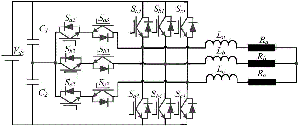
[0044] figure 1A three-level T-type inverter structure diagram is given, including three bridge arms in parallel, each phase bridge arm includes two series-connected IGBT switch tubes, and two IGBT switches in different directions are connected in series on one side of the midpoint of each phase bridge arm. The other side of the IGBT tube is connected to the load; the same DC voltage source is connected to each bridge arm end in parallel; the midpoint of the two midpoint clamping capacitors connected in parallel to the input voltage source is connected to the two directions of each phase bridge arm in different directions One end of the IGBT tube; each IGBT tube is driven by the control circuit.

[0045] A combined method of dead zone elimination and dead zone compensation for a three-level T-type inverter, the met...


PUM


Abstract

The invention discloses a combined method of dead zone elimination and dead zone compensation for a three-level T-type inverter. The method comprises the following steps: respectively adopting different control strategies according to two different stages of the phase current, namely, when the phase current is greater than the set threshold value, adopting a dead zone elimination strategy to change the output phase voltage only by modifying the on-off state of one of switching tubes; and when the phase current near the zero crossing point is smaller than the threshold value, adopting a dead zone compensation strategy at this time, namely, inserting the dead zone time during a sequential switching process, and then adjusting the corresponding vector action time to eliminate the voltage difference and harmonic influence caused by dead zones. Compared with a traditional space vector modulation method, the method disclosed by the invention is small in amount of calculation and simple to implement, cannot affect the closed-loop control, does not need additional hardware circuits, is fast in dead zone compensation speed, and is stable in the conversion process of two control modes. By adopting the method disclosed by the invention, the output voltage difference can be further reduced, the total current harmonic distortion rate can be significantly reduced, and the modulation index cannot be decreased.

Description

technical field [0001] The invention relates to the field of photovoltaic grid-connected inverter technology, in particular to a method for combining dead zone elimination and dead zone compensation of a three-level T-type inverter. Background technique [0002] With the rapid development of distributed power, energy storage systems, electric vehicles and other fields, the requirements for power quality and system efficiency are also getting higher and higher. Compared with the traditional two-level inverter, the three-level inverter has the advantages of less harmonics, less voltage stress of the switching tube, high withstand voltage, and less electromagnetic interference. Compared with other three-level neutral-point clamped inverters, the T-type inverter has two main advantages: when the output phase voltage is DC bus voltage and zero, only one switch is turned on, reducing the Turn-on loss; the average current flowing through each switch tube is equal, and each switch ...

Claims


Application Information

Patent Timeline
IPC IPC(8): H02M7/483H02M7/5395
CPCH02M7/483H02M7/5395
Inventor 康龙云冯腾胡毕华吴璟玥王则沣冯元彬
Owner SOUTH CHINA UNIV OF TECH
Learn More