
Centrifugal Floatation Dry Separator

A centrifugal sorting and sorting machine technology, which is applied in centrifuges, centrifuges with rotating drums, etc., can solve the problems of complex processing technology, high cost of dust removal and high production costs, and achieves simple sorting process and high production cost. Low production cost and satisfactory sorting effect

Inactive Publication Date: 2019-03-29
周国亮
View PDF11 Cites 0 Cited by
  • Summary
  • Abstract
  • Description
  • Claims
  • Application Information

AI Technical Summary

Problems solved by technology

[0003] The above methods of sorting mineral materials all require medium (heavy medium, water, or air) to participate in the sorting process. The process is complicated, there are many auxiliary links and equipment, and the environment is polluted. The sorting equipment used is not only expensive, but also Moreover, there are defects such as high energy consumption, high use cost, inconvenient operation and low sorting efficiency.
The beneficiation method in which water participates in the sorting, the water content of the concentrate increases after sorting, the minerals are cemented and the treatment process is complicated, and the production cost is high
Compressed gas or high-speed air flow participates in the sorting method, which has the problem of air pollution. The current dust removal equipment cannot completely remove the dust, especially the ultra-fine dust particles. Therefore, the huge amount of dust generated by large-scale industrial production will cost a lot in the follow-up dust removal process. high, unsatisfactory

Method used

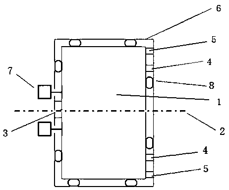
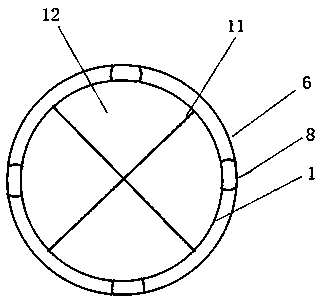

Image

  • Centrifugal Floatation Dry Separator
  • Centrifugal Floatation Dry Separator
  • Centrifugal Floatation Dry Separator

Examples


Embodiment 1

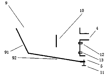
[0031] In this example, see figure 2 , The centrifugal separation chamber 1 is provided with a mineral guide plate 9 between the feed port 3 and the heavy product discharge port 5 . In the present embodiment, the mineral material guide plate 9 includes a feed plate 91 extending obliquely along the edge of the feed port 3 to the inner wall of the centrifugal separation chamber 1 in the circumferential direction, and one end is connected to the feed plate 91, and the other end extends obliquely to the heavy product. The feeding plate 92 on the outside of the discharge opening 5. The purpose is that, adopting this kind of structural design, the ore material entering from the feed port 3 can be vibrated and stratified, while comprehensively transitioning towards the light product discharge port 4 and the heavy product discharge port 5, so that the stratified ore The material can be discharged quickly and evenly, effectively preventing accumulation. It can be foreseen that adjus...

Embodiment 2

[0033] In this example, see figure 2 , The centrifugal separation chamber 1 is provided with a material dividing partition 10 between the light product discharge port 4 and the heavy product discharge port 5 . In this embodiment, the material dividing partition 10 is placed vertically, and is located at the axial center of the centrifugal separation chamber 1 slightly close to the light product discharge port 4 and the heavy product discharge port 5 . The purpose is that after the mineral material is stratified, the high-density granular material is hindered by the material distribution partition 10, falls to the mineral material guide plate 9, and is discharged from the heavy product discharge port 5. Under the action of the material, it crosses the material dividing partition 10, and discharges from the light product discharge port 4, and finally also plays the function of improving the separation speed and accuracy. It can be foreseen that adjusting the structure and hori...

Embodiment 3

[0035] In this example, see figure 2 , The light product discharge port 4 and the heavy product discharge port 5 are provided with a discharge volume controller 11 for adjusting the size of the discharge port. The discharge volume controller 11 can adopt manual or automatic control mode, and adjust the corresponding opening size according to the quantity of high-density and low-density granular materials to be discharged, so as to ensure the sorting efficiency of the whole equipment.


PUM


Abstract

The invention provides a centrifugal floating dry method sorting machine which comprises a centrifugal sorting chamber. The centrifugal sorting chamber is supported on a rotary shaft. A feed inlet is arranged in one side of the centrifugal sorting chamber along the axial direction of the rotary shaft. A light product discharge port and a heavy product discharge port are arranged in the edge of the other side. The heavy product discharge port is far away from the axis, while the light product discharge port is close to the axis. A load bearing bracket is arranged outside the centrifugal sorting chamber. An exciter is arranged at a part, which is close to the feed inlet, of the load bearing bracket. The exciter is fixedly connected with the centrifugal sorting chamber through the load bearing bracket. An elastic cushioning device is arranged between the outer wall of the centrifugal sorting chamber and the inner wall of the load bearing bracket. According to the invention, the centrifugal force of mineral materials is different due to different density; material particles constantly carry out relative movement in a vibration environment; the total bit energy of a mixture tends to the lowest value; sorting is carried out according to density stratification; full grain selection of mineral raw materials is realized; the machine completes the whole process of sorting; and the centrifugal floating dry method sorting machine has the advantages of simple process, equipment miniaturization, clean production and low energy consumption, and is free of media participation.

Description

technical field [0001] The invention relates to a sorting equipment for mines, in particular to a centrifugal floating-sinking dry sorting machine. Background technique [0002] In the prior art, methods for sorting ore materials based on density differences mostly adopt dense medium beneficiation, jigging beneficiation, chute and shaker beneficiation, wind beneficiation and other beneficiation methods. Among them, dense medium beneficiation is based on Archimedes' principle, and the materials to be sorted are placed in dense medium for separation. The sorting equipment mainly includes dense medium cyclone. Jig beneficiation refers to the process of sorting materials according to the density difference in the variable speed medium flow of vertical lifting, and the sorting equipment mainly includes jig machines. The chute and shaking table beneficiation refers to the separation of the difference in the movement state of the ore particles in the inclined water flow, and the s...

Claims


Application Information

Patent Timeline
Patent Type & Authority Patents(China)
IPC IPC(8): B04B3/06B04B11/00
CPCB04B3/06B04B11/00
Inventor 周国亮
Owner 周国亮
Learn More