
Method for Establishing Mesh Model of Welded Hybrid Bidirectional Transition Elements

A technology of cell grid and establishment method, applied in the direction of instrument, design optimization/simulation, calculation, etc., can solve the problems of cell model difficulty, insufficient cell flexibility, large cell length and width, etc., so as to improve the density transition efficiency and reduce the calculation Time cost, effect of reducing the number of units

Active Publication Date: 2019-11-05
CHONGQING UNIVERSITY OF SCIENCE AND TECHNOLOGY
View PDF2 Cites 0 Cited by
  • Summary
  • Abstract
  • Description
  • Claims
  • Application Information

AI Technical Summary

Problems solved by technology

[0003] The traditional dense-to-sparse transition process (only for hexahedron) using geometric sequence node distribution has a large number of elements and high computational cost, which is not practical in complex models or multi-layer multi-pass welding.
As a result, the grid division method of the transition unit is produced. The existing unit transition form has a one-way transition, which is divided into two transition modes: 2:1 and 3:1; this one-way transition mode has the following problems: The ratio of length to width is large; with the densification of the grid in the weld area, the aspect ratio of the unit is very large, and the number of units is large, so this unit is only suitable for models with small thickness, the number of layers of units is small, and the number of units in the weld area Non-intensive welding calculations, not suitable for dense finite element welding calculations in thick plates and weld areas
However, this unit mesh model also has the following problems: there is also the problem of large aspect ratio; when calculating welding residual stress and deformation, due to the anisotropy of the transition unit mesh, the accuracy of the calculation results is low; The flexibility is not good enough to adjust the transition mode according to the actual model to achieve flexible processing
In addition, the existing welding finite element model has a 3:1 bidirectional transition element, which is a hexahedral 3:1 transition in the thickness and width directions. The establishment of the grid is developed by C++ programming and combined with commercial software. Some of the above problems, but there is still insufficient flexibility in unit establishment, and the versatility is not strong in the finite element analysis of thick and thin welded structures, and it is difficult to establish this unit model

Method used


Image

  • Method for Establishing Mesh Model of Welded Hybrid Bidirectional Transition Elements
  • Method for Establishing Mesh Model of Welded Hybrid Bidirectional Transition Elements

Examples


Embodiment 1

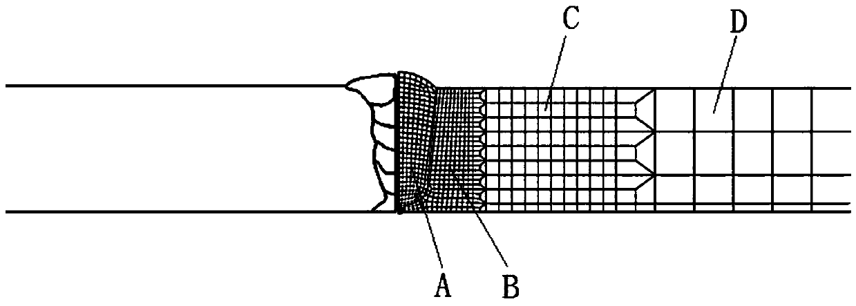
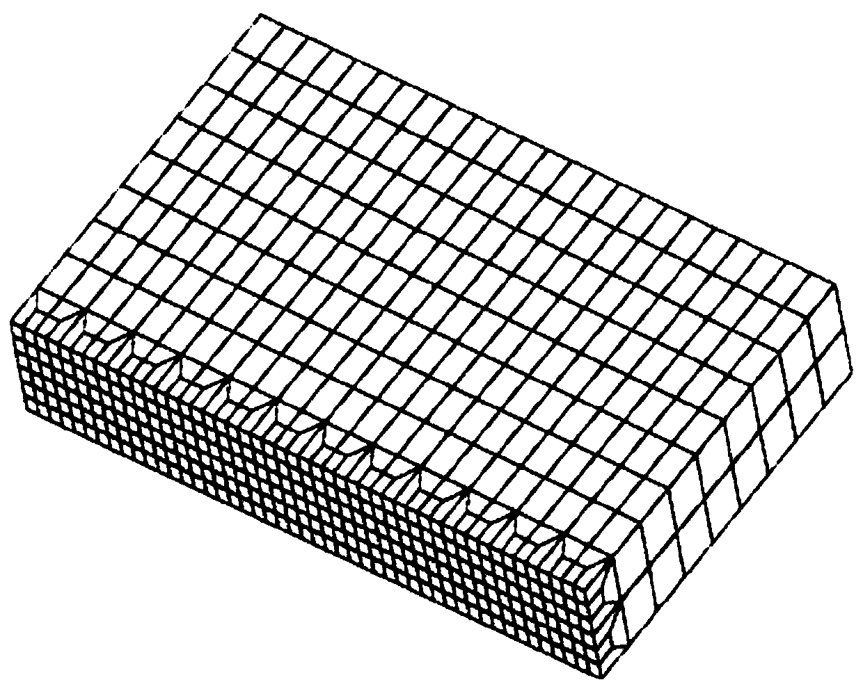
[0030] A method for establishing a welded mixed bidirectional transition cell mesh model, comprising the following steps:

[0031] Step 1. Establish a three-dimensional welding structure geometric model and divide it into weld zone, near weld zone, transition zone and far weld zone;

[0032] Step 2, further dividing the geometric model into minimum geometric model components;

[0033] Step 3, further cutting the transition zone part of the minimum geometric model component into cuboid finite element cells;

[0034] Step 4, dividing the minimum geometric model components from the far welding area to the welding seam area in turn for solid finite element mesh division;

[0035] Step 5, spatially copy the finite element mesh model of the smallest geometric model component, and completely coincide with the three-dimensional geometric model;

[0036] Step 6. Merge the entire finite element model with duplicate nodes, delete the 3D geometric model, and complete the modeling, such ...

Embodiment 2

[0046] In the case of high mesh density at the weld, multiple bidirectional transition units can also be used for density transition, such as figure 2 shown.


PUM


Abstract

The invention provides a building method for a welded mixed two-way transition unit grid model. The method comprises the following steps: I, building a geometrical model with a three-dimensional welding structure, and partitioning the geometrical model into a welding joint area, a near welding area, a transition area and a far welding area; II, further partitioning the geometrical model into minimum geometrical model components; III, further segmenting transition area parts of the minimum geometrical model components into rectangular finite element cell bodies; IV, performing entity finite element grid partition on the minimum geometrical model components from the far welding area to the welding joint area in sequence; V, performing space copying on finite element grid models of the minimum geometrical model components, so that the finite element grid models are coincided completely with a three-dimensional geometrical model; and VI, combining duplicate nodes of an entire finite element model, and deleting the three-dimensional geometrical model to finish modeling. The method has the advantages of easiness, convenience, high transition efficiency, high adaptability and regular unit; the calculation time of finite elements is shortened; and the calculation accuracy is increased.

Description

technical field [0001] The invention relates to the field of welding numerical calculation finite element analysis CAE, in particular to a method for establishing a mixed bidirectional transition element grid model for welding finite element analysis. Background technique [0002] Due to the different core algorithms, finite element analysis technology can be divided into two types of calculation and analysis, explicit and implicit (except for fluid). The finite element analysis is based on the element mesh model. Under the same number of elements, the explicit calculation is much faster than the implicit calculation. The implicit calculation solves the equilibrium solution of the stiffness matrix of the entire model at each step; and the implicit calculation follows As the number of grid cells increases, the computational time cost increases exponentially. Welding finite element simulation belongs to implicit calculation, using thermal-mechanical coupling finite element an...

Claims


Application Information

Patent Timeline
Patent Type & Authority Patents(China)
IPC IPC(8): G06F17/50
CPCG06F30/23
Inventor 尹立孟刘成王金钊唐丽王刚姚宗湘夏文堂
Owner CHONGQING UNIVERSITY OF SCIENCE AND TECHNOLOGY
Learn More