Spherical display image processing method and system

A spherical display and image processing technology, applied in image data processing, graphics and image conversion, instruments, etc., can solve the problems of low flexibility, deformation of fisheye head divergence characteristics, low operating efficiency, etc., to achieve flexible display and high efficiency High-quality conversion output, high-efficiency operation effect

Active Publication Date: 2017-04-05
WUXI SEEMILE LASER DISPLAY TECH +1
View PDF10 Cites 10 Cited by
  • Summary
  • Abstract
  • Description
  • Claims
  • Application Information

AI Technical Summary

Problems solved by technology

[0002] The current spherical display technology uses computers, projectors, fisheye lenses and ball screens. The projection signal output by the computer is processed by the projector through imaging technology to become an image output, and the image output by the projector fills the entire ball through the fisheye lens. Under normal circumstances, the picture to be projected (which can be a video or picture) output by the computer to the projector is a flat rectangular image, so the picture output by the projector is also a flat rectangular image, which is directly projected to the ball screen through the fisheye lens On the other hand, it will cause very large deformation due to the strong divergence characteristics of the fisheye lens, which will seriously affect the display effect on the spherical screen
Therefore, it is necessary to perform image transformation on the image and the display model to obtain the final output image. At present, the commonly used transformation method is to convert the image pixels into polar coordinates and then map to the three-dimensional coordinates of the sphere, and then calculate the position of the original image from the three-dimensional coordinates. Flexibility Not high, and the operating efficiency is low, especially for the blind spots that cannot be handled in the processing of some ball screen vertices and bottom points

Method used


Image

  • Spherical display image processing method and system
  • Spherical display image processing method and system
  • Spherical display image processing method and system

Examples


Embodiment Construction

[0026] Embodiments of the present invention are described below through specific examples, and those skilled in the art can easily understand other advantages and effects of the present invention from the content disclosed in this specification. The present invention can also be implemented or applied through other different specific implementation modes, and various modifications or changes can be made to the details in this specification based on different viewpoints and applications without departing from the spirit of the present invention. It should be noted that, in the case of no conflict, the embodiments in the present application and the features in the embodiments can be combined with each other.

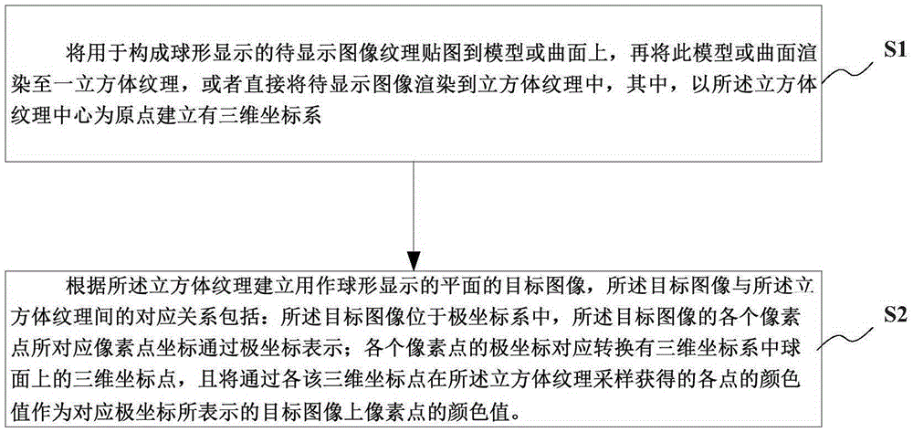
[0027] Such as figure 1 As shown, the present invention provides a spherical display image processing method, comprising:

[0028] Step S1: Map the image to be displayed to form a spherical display as a texture on the model or surface, and then render the model or surface...


PUM


Abstract

The invention provides a spherical display image processing method and system, and the method comprises the steps: enabling a to-be-displayed image to serve as a texture map and to be pasted on a model or a curved surface, and rendering the model or curved surface till a cubic texture or directly carrying out rendering; building a target image of a plane for spherical display according to the cubic texture, wherein the corresponding relation between the target image and the cubic texture is that the target image is located in a polar coordinate system and the pixel coordinates corresponding to each pixel of the target image are expressed through polar coordinates; enabling the polar coordinates of each pixel to be correspondingly converted into a three-dimensional coordinate point on the a spherical surface in a three-dimensional coordinate system, and enabling the color value, obtained through the sampling of the cubic texture at each three-dimensional coordinate point, of each point to be given to a corresponding pixel of the target image; carrying out the algorithm transformation in an actual implementation process with the help of a top point shader of a graphic platform directx or opengl, and achieving the high-efficiency and high-quality conversion output through a graphic display card, thereby enabling display to have no blind region, enabling display to be flexible, and enabling the operation efficiency to be high.

Description

technical field [0001] The invention relates to the technical field of image display, in particular to a spherical display image processing method and system. Background technique [0002] The current spherical display technology uses computers, projectors, fisheye lenses and ball screens. The projection signal output by the computer is processed by the projector through imaging technology to become an image output, and the image output by the projector fills the entire ball through the fisheye lens. Under normal circumstances, the picture to be projected (which can be a video or picture) output by the computer to the projector is a flat rectangular image, so the picture output by the projector is also a flat rectangular image, which is directly projected to the ball screen through the fisheye lens On the other hand, it will cause very large deformation due to the strong divergence characteristics of the fisheye lens, which will seriously affect the display effect on the sph...

Claims


Application Information

Patent Timeline
Patent Type & Authority Applications(China)
IPC IPC(8): G06T3/00
CPCG06T3/005
Inventor 袁学忠陈龙
Owner WUXI SEEMILE LASER DISPLAY TECH
Why Eureka
Try Eureka