Circuit converter control system

A control system and converter technology, applied in the direction of irreversible AC power input conversion to DC power output, etc., can solve the problems of limitation, lack of flexibility, inconvenient use, etc., and achieve the effect of avoiding overshoot

Inactive Publication Date: 2017-04-05
JOINT POWER EXPONENT
View PDF5 Cites 3 Cited by
  • Summary
  • Abstract
  • Description
  • Claims
  • Application Information

AI Technical Summary

Problems solved by technology

However, generally speaking, the design of such an analog circuit is relatively inflexible. Specifically, if the circuit converter PA2 is to be operated in a continuous conduction mode (Continuous Conduction Mode, CCM), a discontinuous conduction mode (Discontinuous Conduction Mode, DCM) or Boundary Conduction Mode (Boundary Conduction Mode, BCM), when the circuit needs to be modified, it is limited by the structure of the analog circuit and cannot be reprogrammed, so it is necessary to redesign the internal circuit and the compensation circuit PA26, so that in practice, the less convenient to use

Method used


Image

  • Circuit converter control system
  • Circuit converter control system
  • Circuit converter control system

Examples


Embodiment Construction

[0055] Since in the circuit converter control system provided by the present invention, there are numerous combination implementations, so they will not be repeated here, but only a preferred embodiment is given for specific description.

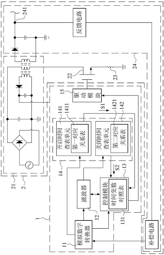
[0056] see figure 2 , figure 2 It is a block diagram showing a circuit converter control system and a circuit converter according to a preferred embodiment of the present invention.

[0057] As shown in the figure, the circuit converter control system 1 of the preferred embodiment of the present invention is electrically connected to a circuit converter 2, and the circuit converter 2 can be a flyback converter, but other embodiments are not limited to this, The circuit converter 2 includes an input stage circuit 21 , a load switch 22 , a load resistor 23 and an output stage circuit 24 . The input stage circuit 21 generally includes an AC power supply, a bridge rectifier, a bulk capacitor, and an inductor. , diodes, capacitors and transfo...


PUM


Abstract

The invention provides a circuit converter control system which is electrically connected to a circuit converter including an input stage circuit, a load switch and an output stage circuit. In the circuit converter control system, a filter is sued for sampling a historical feedback average voltage according to feedback output voltages at different times for digital signals output by an output end at different times; a control module is provided with a voltage threshold, and is used for receiving immediate feedback output voltages for the digital signals output by the output end and detecting the load state of the circuit converter based on the historical feedback average voltage; and the control module controls the load switch at a control duty cycle, increases the control duty cycle for controlling the load switch when the load state is changed from a light load state to a heavy load state and the voltage difference value reaches the voltage threshold, otherwise reduces the control duty cycle. Therefore, the need for time-consuming circuit redesign is not required, and the problem of overshoot and load reduction of the circuit converter can be effectively solved.

Description

technical field [0001] The invention relates to a circuit converter control system, in particular to a circuit converter control system which adopts digital circuit control and adjusts the duty cycle according to the light load state and the heavy load state. Background technique [0002] With the rapid advancement of science and technology, electronic devices have been flooded in people's lives. Among them, with the energy-saving form of consumer electronics and the emphasis on environmental protection, electronic products are required to consume low power during standby to prolong battery life. and reduce power consumption, so how to design circuit converters has become a problem to be solved in the industry. [0003] see figure 1 , figure 1 In order to show a schematic block diagram of a power converter in the prior art of the present invention, generally, a flyback circuit converter includes an analog pulse width modulation (Pulse WidthMoulation, PWM) control switching...

Claims


Application Information

Patent Timeline
Patent Type & Authority Applications(China)
IPC IPC(8): H02M7/12
Inventor 颜业烜赖致廷
Owner JOINT POWER EXPONENT
Why Eureka
Try Eureka