
Method for selecting particle size distribution ranges and filling amount ratio of heat-conducting silica gel thermal interface material powder filler

A technology of thermal interface material and powder filler, applied in the field of thermally conductive silica gel thermal interface material, can solve the problems of low thermal conductivity and non-dense powder particles, and achieve an increase in bulk density, a reduction in porosity, and a strong theoretical guidance. Effect

Active Publication Date: 2017-04-19
SHANGHAI UNIV
View PDF3 Cites 11 Cited by
  • Summary
  • Abstract
  • Description
  • Claims
  • Application Information

AI Technical Summary

Problems solved by technology

When the filling amount of the thermally conductive filler is large, although the powder particles form a thermally conductive network chain, the gaps between the powder particles become an unavoidable problem, resulting in the filling of the thermally conductive polymer composite powder particles. Non-dense, low thermal conductivity and other issues

Method used


Image

  • Method for selecting particle size distribution ranges and filling amount ratio of heat-conducting silica gel thermal interface material powder filler
  • Method for selecting particle size distribution ranges and filling amount ratio of heat-conducting silica gel thermal interface material powder filler
  • Method for selecting particle size distribution ranges and filling amount ratio of heat-conducting silica gel thermal interface material powder filler

Examples


Embodiment 1

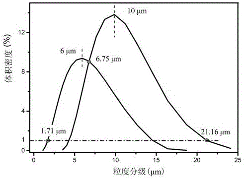
[0034] Embodiment 1: Select two kinds of thermally conductive powder fillers with different particle size distribution ranges, and use two different particle size distribution ranges of 10 μm and 6 μm (such as figure 1 ) aluminum powder filler for multi-scale compounding, using the Dinger-Funk closest packing equation to calculate the volume percentage of aluminum powders with two different particle sizes when compounding, the process is as follows:

[0035] First, determine the distribution range of the particle size of the thermally conductive powder filler: the distribution range of the 6 μm particle size is [1.71, 6.75], and the distribution range of the 10 μm particle size is [6.75, 21.16].

[0036] Then, the Dinger-Funk closest packing equation: Among them, in the composite heat-conducting powder filler system D max =21.16,D min =1.71, n=0.37, U(D p ) value by D p Get the value, as shown in the following table:

[0037]

[0038]

[0039] Therefore, it is conclu...

Embodiment 2

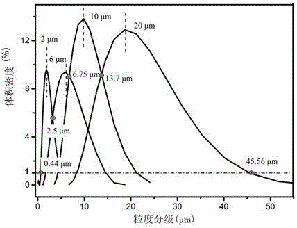
[0049] Embodiment 2: Select four kinds of thermally conductive powder fillers with different particle size distribution ranges, and four different particle size distribution ranges of 20 μm, 10 μm, 6 μm and 2 μm (such as figure 2 ) for multi-scale compounding of aluminum powder fillers, using the Dinger-Funk closest packing equation to calculate the volume percentage of aluminum powder fillers with four different particle sizes when compounding, the process is as follows:

[0050] First, determine the distribution range of the particle size of the thermally conductive powder filler: the distribution range of the 2μm particle size is [0.44,2.5], the distribution range of the 6μm particle size is [2.5,6.75], and the distribution range of the 10μm particle size is [6.75,13.7], the distribution range of 20μm particle size is [13.7,45.56].

[0051] Then, the Dinger-Funk closest packing equation: Among them, in the composite heat-conducting powder filler system D max =45.56,D m...

Embodiment 3

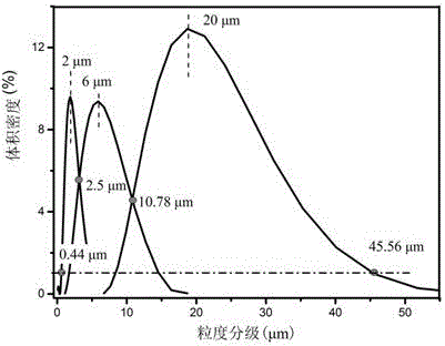
[0062] Three thermally conductive powder fillers with different particle size distribution ranges are selected, and three different particle size distribution ranges of 20 μm, 6 μm and 2 μm (such as image 3 ) aluminum powder fillers for multi-scale compounding, using the Dinger-Funk closest packing equation to calculate the volume percentage of aluminum powder fillers with three different particle sizes when compounding, the process is as follows:

[0063] First, determine the distribution range of the particle size of the thermally conductive powder filler: the distribution range of the 2μm particle size is [0.44,2.5], the distribution range of the 6μm particle size is [2.5,10.78], and the distribution range of the 20μm particle size is [10.78, 45.56].

[0064] Then, the Dinger-Funk closest packing equation: Among them, in the composite heat-conducting powder filler system D max =45.56,D min =0.44, n=0.37, U(D p ) value by D p The value is obtained, as shown in the fol...


PUM

PropertyMeasurementUnit
Apparent densityaaaaaaaaaa
Thermal conductivityaaaaaaaaaa
Apparent densityaaaaaaaaaa

Abstract

The invention discloses a method for selecting particle size distribution ranges and the filling amount ratio of heat-conducting silica gel thermal interface material powder filler. The method comprises the following steps of 1, selecting several types of heat-conducting powder filler different in particle size distribution range; 2, selecting the particle size distribution ranges and the filling amount ratio of the heat-conducting powder filler different in particle size distribution range; 3, adding the heat-conducting filler different in particle size distribution range into a silicone rubber base body in sequence from large particle size to small particle size according to the determined filling amount ratio, and conducting uniform mixing by mechanical manners such as stirring or smelting or banburying, so that a heat-conducting powder filler and silicone rubber mixture is obtained; and 4, further improving density of the silicone rubber mixture through a physical vibration method. The method for theoretically researching the filling amount ratio of the heat-conducting powder filler different in particle size distribution range is mainly provided. By means of the research method, a silicone rubber thermal interface material which is high in powder filler stacking density, high in heat conductivity coefficient and stable in performance can be prepared. The method has great theoretical instruction significance for selection of types and particle sizes of the powder filler and optimization of the filling amount of the heat-conducting powder filler different in particle size distribution range.

Description

technical field [0001] The invention relates to a method for selecting the particle size distribution range and filling ratio of fillers for thermal conductive silica gel thermal interface material powder with high thermal conductivity, high packing density and good stability. The invention belongs to the technical field of heat-conducting silica gel thermal interface materials. [0002] technical background [0003] In recent years, with the continuous improvement of the integration level and assembly density of electronic components, while electronic products provide high-performance and high-efficiency, the power consumption and operating temperature of each component have also increased sharply. The stability and reliability of the device will have harmful effects, which will greatly shorten the service life of the component. In order to ensure the stable and reliable operation of electronic components for a long time, it is necessary to prevent the continuous rise of th...

Claims


Application Information

Patent Timeline
IPC IPC(8): C08L83/04C08K3/08C08K3/22
CPCC08K3/08C08K3/22C08K2003/0812C08K2003/085C08K2003/2227C08K2003/2296C08K2201/003C08K2201/014C08L83/04
Inventor 王金合施利毅赵迪邹雄毛琳
Owner SHANGHAI UNIV
Learn More