Method for fixing blades of wind blade spoke-type wind wheel electricity generation device, device and electricity generation device

A technology of a power generation device and a fixing method is applied in the field of a wind impeller-spoke type wind turbine power generation device and a planetary gear eccentric lever-driven energy-saving gearbox, which can solve the problems of difficult market-oriented operation of wind power energy, low wind energy efficiency, and poor power generation efficiency. Achieve the effect of stable and reliable power generation quality, large installed capacity and large torsional force

Active Publication Date: 2017-04-19
王龙宝
View PDF11 Cites 1 Cited by
  • Summary
  • Abstract
  • Description
  • Claims
  • Application Information

AI Technical Summary

Problems solved by technology

It is really because the wind energy efficiency of the existing three sharp-knife blade structure is low, resulting in high cost of wind power and poor power generation efficiency. It needs to rely on state subsidies and incentives to operate, making it difficult for wind power energy to enter market-oriented operation.

Method used


Image

  • Method for fixing blades of wind blade spoke-type wind wheel electricity generation device, device and electricity generation device
  • Method for fixing blades of wind blade spoke-type wind wheel electricity generation device, device and electricity generation device
  • Method for fixing blades of wind blade spoke-type wind wheel electricity generation device, device and electricity generation device

Examples


Embodiment 1

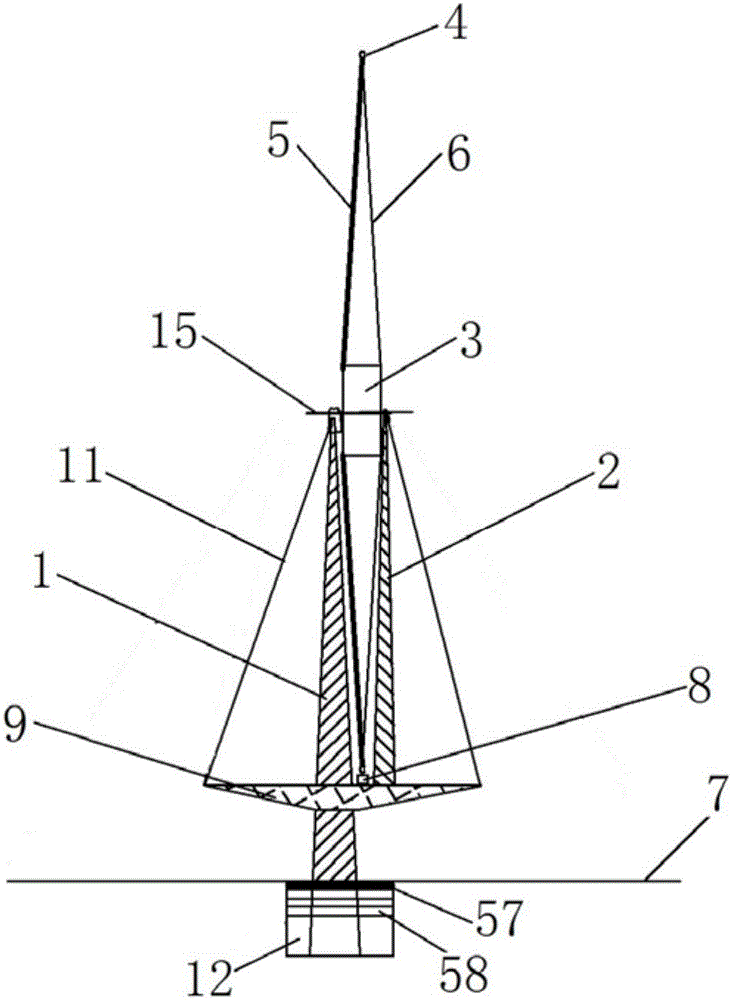
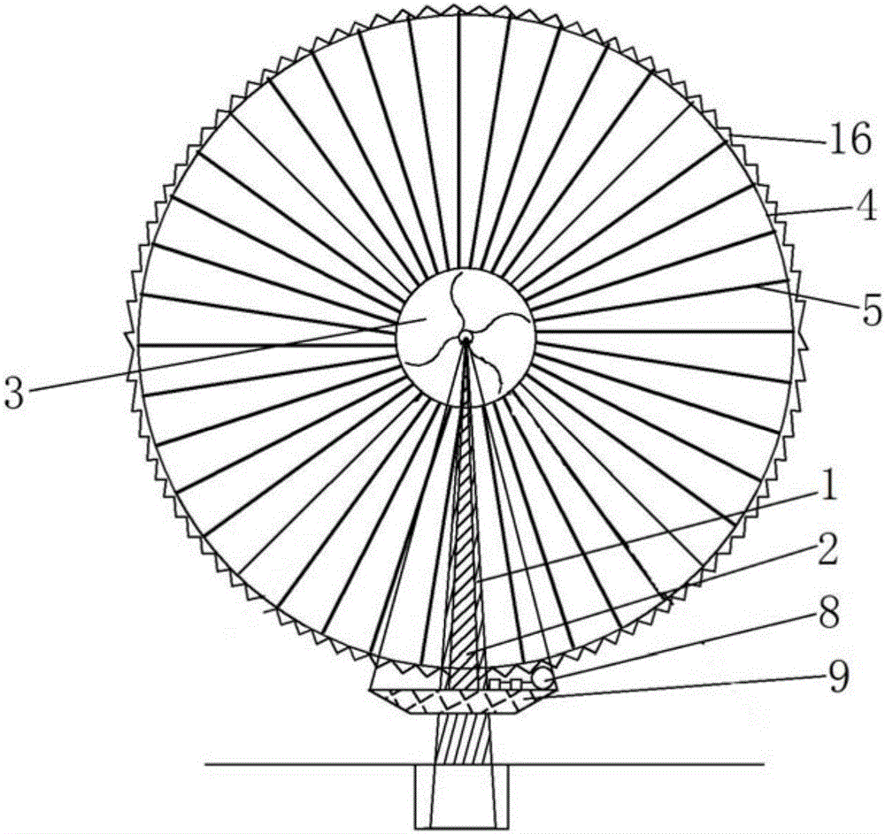
[0049] like figure 1 and 2 Shown is a schematic structural view of the wind turbine power generation device of Embodiment 1. The wind turbine generating device includes: a tower column, a wind rotor, a driven wheel, a planetary gear eccentric drive gearbox, multiple generators and a steering system.

[0050] The wind wheel includes a central hub 3 , an outer rim 4 , several blades 5 and several first stay cables 6 .

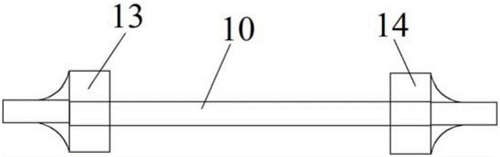
[0051] like image 3 As shown, the central hub 3 includes a shaft cylinder 10 and two ends of the hubs. The two ends of the hubs are a first hub 13 and a second hub 14 . One end of each blade 5 is fixed on the first hub 13 , and the other end is fixed on the outer rim 4 ; one end of each first stay cable 6 is fixed on the second hub 14 , and the other end is fixed on the outer rim 4 .

[0052] The tower system includes a main tower 1 , an auxiliary tower 2 and a first steering platform support frame 9 . The main tower column 1 is fixed on the ground using a ...

Embodiment 2

[0072] like Image 6 Shown is a schematic structural view of the wind turbine power generation device of Embodiment 2. It is different from the structure of Example 1. The central hub includes a shaft cylinder, two ends of the hub and a middle hub 60. The two ends of the hub are the first hub and the second hub. the central segment. One end of each blade 5 is fixed on the middle hub 60, and the other end is fixed on the outer rim 4, and the blade 5 is in a vertical state. One end of each first stay cable 6 is fixed on the first hub or the second hub, and the other end is fixed on the outer rim 4 .

[0073] In Embodiment 2, the tower system includes a fixed tower shaft 22 , a second steering platform support frame 20 , a front tower column 21 and a rear tower column 62 . The fixed tower shaft 22 is arranged on the ground 7 . The second steering platform support frame 20 is rotatably arranged on the fixed tower shaft 22 . The front tower column 21 and the rear tower column...

Embodiment 3

[0076] like Figure 7 and 8 As shown, it is a structural schematic diagram of different fixing methods of the blade of the present invention.

[0077] Figure 7 Among them, one end of the blade 5 is fixed on the hub of the middle section, and the other end is fixed on the outer rim 4 via the fourth stay cable 24 . In the middle of the blade 5 , it is fixed at the first fixed point 27 of the blade through the fifth stay cable 26 , and is fixed at the second fix point 29 of the blade through the sixth stay cable 28 . The other ends of the fourth stay cable 24 , the fifth stay cable 26 and the sixth stay cable 28 are respectively fixed on the hubs at both ends. In addition, there are front and rear support rods 23 between the fourth stay cables 24 , and the two ends of the front and rear stay stay rods 23 are cross-fixed on the hubs at both ends via the seventh stay cables 30 and the eighth stay cables 31 .

[0078] Figure 8 Among them, one end of the blade 5 is fixed on th...


PUM


Abstract

The invention discloses a method for fixing blades of a wind blade spoke-type wind wheel electricity generation device. The fixing method is implemented by fixing one end of a blade on an outer wheel rim and the other end on a center wheel hub so as to fix two ends of the blade. The invention also discloses a device for fixing blades of a wind blade spoke-type wind wheel electricity generation device. The invention also discloses a wind blade spoke-type wind wheel electricity generation device. The invention also discloses a planetary gear eccentric driving energy saving gear case. A driving structure is installed on a wind wheel outer wheel rim to form an electricity generation transmission mode of an outer wheel rim flywheel-type main driving wheel driving an energy saving gear case at high linear speed; the present electricity generation mode of a wind wheel center driving a step-up gear case at a slow rotating speed is changed; at the same time, the wind wheel electricity device is provided with functions such as inertia effect, energy storage and stable speed of giant flywheels.

Description

technical field [0001] The invention relates to the technical field of design and manufacture of new energy wind power equipment, in particular to a method for fixing blades of a wind turbine generator, a blade fixing device of a wind turbine generator, a blade spoke type wind turbine generator including the blade fixing device, and a planetary generator. The gear eccentric lever drives the energy-saving gearbox. Background technique [0002] Energy is a matter of great importance to all mankind. It is related to people's livelihood, happiness and well-being, and it is related to the beauty, prosperity and strength of the country. Since human beings entered the technological society, the demand for energy has been increasing. The environmental pollution caused by a large amount of non-renewable energy has been increasing, which has affected the global natural environment and severe climate changes, affecting the quality of human life. Therefore, it is imminent to seek clea...

Claims


Application Information

Patent Timeline
Patent Type & Authority Applications(China)
IPC IPC(8): F03D1/06F03D9/25F03D15/00F03D13/20F16H1/32
CPCF03D1/0658F03D1/0691F16H1/32F05B2260/40311F16H2001/327F16H2001/323Y02E10/72
Inventor 王龙宝王芳芳王昱权
Owner 王龙宝
Why Eureka
Try Eureka