Rubbing acoustic emission denoise method based on empirical wavelet transform

An empirical wavelet and acoustic emission technology, applied in the direction of measuring devices, instruments, special recording/indicating devices, etc., can solve problems that do not meet high-frequency signal resolution, application limitations, signal mode mixing, etc., and achieve signal High noise, obvious noise cancellation effect, filter out the effect of modal aliasing

Pending Publication Date: 2017-04-19
SOUTHEAST UNIV
View PDF6 Cites 14 Cited by
  • Summary
  • Abstract
  • Description
  • Claims
  • Application Information

AI Technical Summary

Problems solved by technology

However, there are defects in these methods: once the window function is selected in the short-time Fourier transform, its time-frequency resolution is fixed, which does not meet the high-frequency signal resolution and should be higher than the low-frequency signal resolution. high practical requirements
Although the Winger-Ville distribution has a high time-frequency resolution, its application is greatly limited due to the existence of cross-term interference for multi-component signals.
Wavelet transform has the characteristics of multi-resolution, but it needs to artificially select the wavelet base in the application, so it lacks adaptability, and it cannot solve the problem of low-frequency interference well
Empirical Mode Decomposition (EMD) can adaptively decompose non-stationary signals, but there are still some defects. It is an empirical method and still lacks a complete theoretical basis. The orthogonality of the modal components still needs to be demonstrated; the end judgment standard of its decomposition through the envelope is not scientific, which may cause the problem of modal aliasing in the decomposed signal; it takes multiple iterations to obtain the complete IMF Portion, time-consuming, large amount of calculation

Method used


Image

  • Rubbing acoustic emission denoise method based on empirical wavelet transform
  • Rubbing acoustic emission denoise method based on empirical wavelet transform
  • Rubbing acoustic emission denoise method based on empirical wavelet transform

Examples


Embodiment Construction

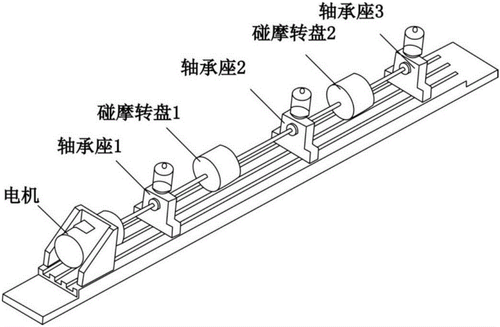
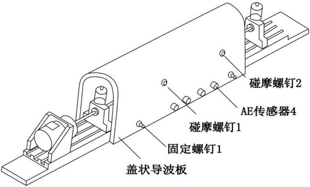
[0050]As shown in Figure 1, the rubbing AE experimental system consists of a rotor rubbing test bench, a sensor, a preamplifier, a governor and an acoustic emission acquisition system. The rotor rubbing test bench is a flexible rotor test bench, which consists of three bearing seats with sliding bearings to support the rotor, two rubbing discs, and rubbing screws. The rubbing screw can point to the center of the rotating shaft through the screw hole on the cover-shaped waveguide plate, and is in contact with the side of the disc. When the rotor rotates at a certain speed, the adjusting rubbing screw rubs against the rubbing disk, and the rubbing acoustic emission signal generated is received by the acoustic emission sensor through the waveguide plate. By adjusting the screw-in depth of the rubbing screw to simulate different intensities of rubbing. The governor realizes the stepless speed regulation of the motor in the range of 0-10000r / min; in order to reduce the distortion ...


PUM


Abstract

The invention discloses a rubbing acoustic emission denoise method based on empirical wavelet transform. The method comprises the following steps that (1) an acoustic emission signal is acquired through a rubbing acoustic emission experimental device; (2) adaptive partition is performed on the acoustic emission signal according to the Fourier spectrum features; (3) a wavelet window is added after partition, and an empirical scale function and an empirical wavelet function are defined; (4) empirical wavelet transform is defined; and (5) wavelet denoising is performed on each empirical mode component fi and then reconstruction is performed based on EWT. The beneficial effects of the rubbing acoustic emission denoise method based on empirical wavelet transform are that adaptive partition is performed according to the Fourier spectrum of the acoustic emission signal, and a wavelet filter bank is constructed to extract different intrinsic mode components included in the acoustic emission signal so that less modes are decomposed and the phenomena of mode aliasing and endpoint effect can be effectively filtered; and wavelet denoising is performed on each empirical mode component, reconstruction is performed based on EWT and denoising is performed on the signal so that the denoised signal has high signal-to-noise ratio and the denoise effect is obvious.

Description

technical field [0001] The invention relates to the field of fault diagnosis of rotating machinery, in particular to an acoustic emission denoising method based on empirical wavelet transform. Background technique [0002] Acoustic emission technology has become a research hotspot in the fault diagnosis of rotating machinery due to its wide response frequency and high sensitivity. However, acoustic emission signals are easily interfered by environmental noise, especially the large amount of interference noise generated during the operation of rotating machinery, which makes useful acoustic emission fault features blurred or even submerged, making it difficult to effectively analyze and diagnose faults. Therefore, it is a prerequisite for effective diagnosis when noise reduction is performed on acoustic emission signals. [0003] The basic method of signal noise reduction processing is filtering. The noise reduction result also broadens the waveform of the signal, and smooth...

Claims


Application Information

Patent Timeline
Patent Type & Authority Applications(China)
IPC IPC(8): G01M13/00G01D3/032
CPCG01M13/00G01D3/032
Inventor 邓艾东张瑞司晓东刘东瀛李晶
Owner SOUTHEAST UNIV
Why Eureka
Try Eureka