Time division multiple access infrared opposite launching type pedestrian passage passing target detection method

A pedestrian channel, infrared opposite-radiation technology, which is applied to measurement devices, uses re-radiation, and electromagnetic wave re-radiation, etc., can solve the problem of unable to detect the correct state of pedestrians in time, unable to obtain anti-interference effects, and increase intermediate connection nodes. To achieve the effect of simplifying the structure, reducing the difficulty of construction and avoiding interference

Inactive Publication Date: 2017-04-19
杭州立方控股股份有限公司
View PDF4 Cites 3 Cited by
  • Summary
  • Abstract
  • Description
  • Claims
  • Application Information

AI Technical Summary

Problems solved by technology

The output signals of the infrared transceiver pairs distributed on both sides of the channel will eventually be connected to the controller. It is not a good way to transmit multiple signals in parallel for a long distance. Usually, all the signals on one side of the channel are state-encoded and then serialized. Line transmission to the controller on the other side increases the intermediate connection nodes, which is not conducive to the reliability of the system; the commercially available integrated infrared transmitter and receiver specially used in the field of infrared detection have a certain response speed, when the channel When the pedestrians are moving fast, the system often cannot detect the correct state of the pedestrians in time
[0004] In order to reduce the mutual influence of adjacent infrared transceivers on the tubes, it is usually necessary to carefully adjust the installation angle of the infrared transceivers on the tubes at the construction site or take additional light isolation measures, which usually cannot achieve the ideal anti-interference effect

Method used


Image

  • Time division multiple access infrared opposite launching type pedestrian passage passing target detection method
  • Time division multiple access infrared opposite launching type pedestrian passage passing target detection method

Examples


Embodiment Construction

[0018] The purpose and effects of the present invention will become more apparent by describing the present invention in detail below with reference to the accompanying drawings.

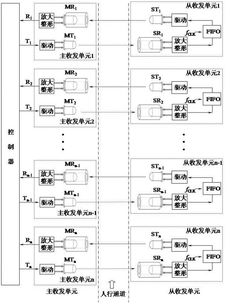
[0019] The present invention is a time-division multiple-access infrared cross-shooting type pedestrian passageway target detection method, the method is implemented on the detection system, such as figure 1 As shown, the detection system includes a controller and multiple sets of infrared light detection pairs; the infrared light detection pair includes a master transceiver unit and a slave transceiver unit relatively placed on both sides of the channel, and the master transceiver unit and the slave transceiver unit each include a An infrared transmitting tube and an infrared receiving tube, the receiving direction of the infrared transmitting tube of the main transceiver unit is consistent with that of the infrared receiving tube of the slave transceiver unit, and the receiving direction of the inf...


PUM


Abstract

The invention discloses a time division multiple access infrared opposite launching type pedestrian passage passing target detection method. One master transceiver unit and one slave transceiver unit oppositely arranged at the two sides of a passage constitute an infrared light detection pair. Multiple infrared light detection pairs are placed along the horizontal direction of the passage. The master transceiver units have functions including infrared light emitting, infrared light receiving, weak signal resonant selected-frequency amplifying, and signal shaping. The slave transceiver units are each additionally provided with an FIFO buffer relative to the master transceiver units. An emitted light pulse and reflected light pulse opposite launching technology based on time division multiple access is employed. The problem that a control detection line must be connected at both sides in infrared light channel detection is solved. A controller can judge whether an infrared transmission channel is smooth by only reading coding data output by the master transceiver units. The structure of the system is simplified. The difficulty of engineering construction is lowered. Adjacent detection pairs work in a staggered manner, so that the interference between adjacent infrared light detection pairs is avoided, and the reliability of the system is improved.

Description

technical field [0001] The invention relates to the technical field of photoelectric detection, in particular to a method for detecting passing objects in a channel in the application field of light. Background technique [0002] At present, light-based detection and control products are widely used in the field of non-contact measurement and control, especially in the field of wireless remote control, safety detection, short-distance It has been widely used in wireless communication and other aspects. [0003] In applications such as automatic ticket checking at stations, entrance and exit detection of large venues, etc., the infrared channel detection method is widely used. Usually, multiple infrared tubes are installed on both sides of the channel. When someone passes in the channel, there will be Part of the pair of tubes is blocked, and through the law of blocking, the controller can identify the direction of pedestrians and the size of the target volume. In the speci...

Claims


Application Information

Patent Timeline
Patent Type & Authority Applications(China)
IPC IPC(8): G01S17/02G01S17/50G01S7/483
CPCG01S7/483G01S17/04G01S17/50
Inventor 卢旭鹏覃勇朱金刚
Owner 杭州立方控股股份有限公司
Why Eureka
Try Eureka