Thimble supporting plate adjustment tool structure and leveling method

A technology for adjusting work and thimbles, which is applied in the direction of electrical components, semiconductor/solid-state device manufacturing, circuits, etc., can solve problems such as the inability to directly adjust the level of thimble support plates, and achieve the effects of avoiding bumps, stabilizing positions, and improving speed and quality

Active Publication Date: 2017-04-19
PIOTECH CO LTD
View PDF4 Cites 3 Cited by
  • Summary
  • Abstract
  • Description
  • Claims
  • Application Information

AI Technical Summary

Problems solved by technology

[0003] The purpose of the present invention is to solve the above problems, mainly to solve the technical problem that the level of the thimble support plate cannot be directly adjusted at present, and to provide a level adjustment tool for the thimble support plate, which reduces the processing difficulty of the thimble support plate adjustment mechanism and simplifies the level adjustment of the thimble support plate Improve the level adjustment accuracy and level adjustment speed of the upper surface of the thimble support plate

Method used


Image

  • Thimble supporting plate adjustment tool structure and leveling method
  • Thimble supporting plate adjustment tool structure and leveling method
  • Thimble supporting plate adjustment tool structure and leveling method

Examples


Embodiment

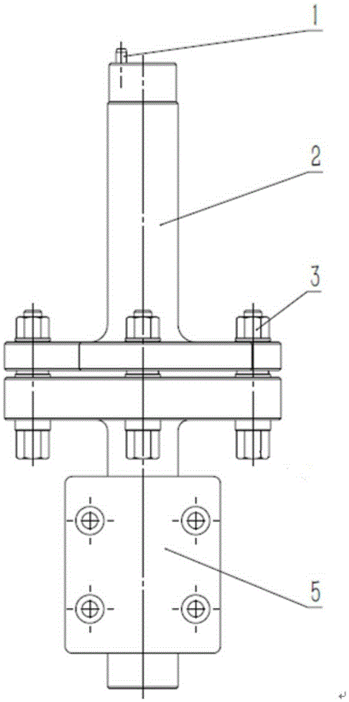
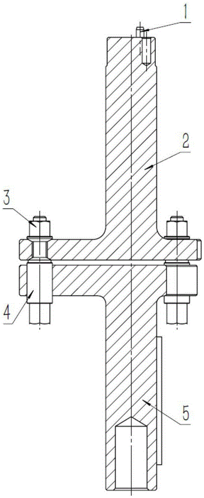
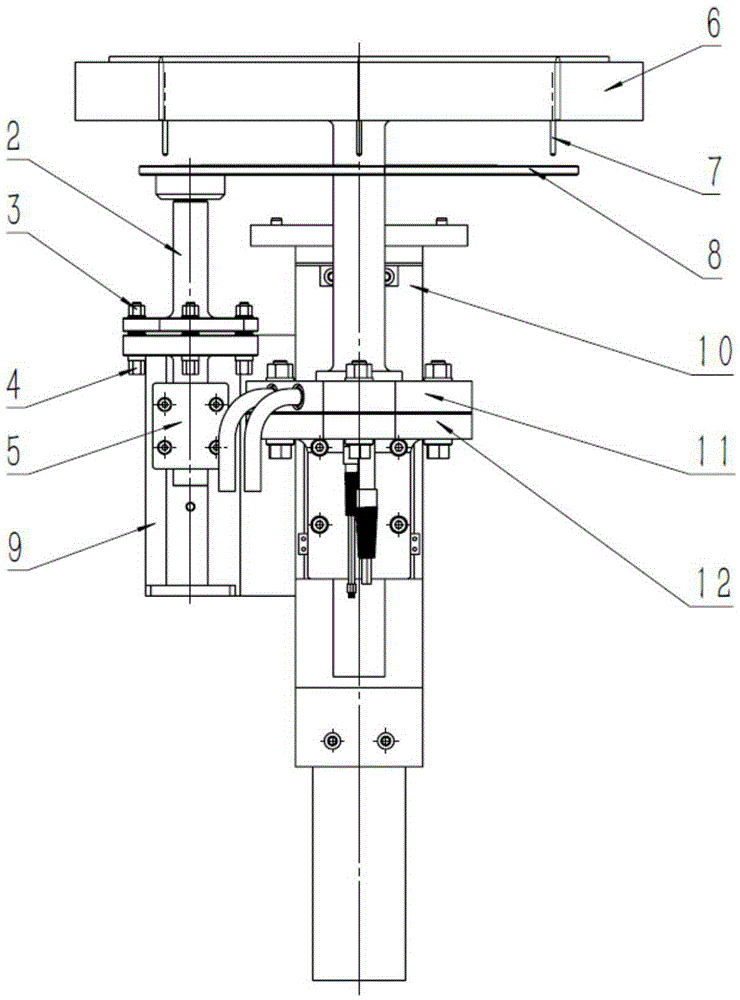
[0017] Reference Figure 1-3 , The thimble support plate adjustment tooling structure, including: positioning pin 1, support rod 2, adjustment nut 3, adjustment bolt 4 and support 5. The support 5 is fixed on the sliding block and drives the thimble support plate adjustment tool to slide on the base 9. The support 5 is provided with three threaded holes uniformly distributed at 120° for adjusting the level of the thimble support plate 8 in cooperation with adjusting bolts. The adjusting bolt 4 adopts fine thread. The rotating bolt 4 adjusts the relative height of the support rod 2 and the support 5, adjusts the level of the upper surface of the thimble support plate 8, and rotates the adjusting bolt 4 once to adjust the height of a pitch. A gasket is installed at the position where the support rod 2 and the support 5 are connected, and an adjustment nut 3 is installed above the gasket. The adjustment nut 3 can ensure that the thimble support plate 8 is always kept horizontal d...


PUM


Abstract

The invention relates to a thimble supporting plate adjustment tool structure and a leveling method and aims to solve a horizontal adjustment problem of an upper surface of a thimble supporting plate. The tool structure comprises a positioning pin, a supporting rod, an adjusting nut, an adjusting thread bolt and a supporting seat, wherein the positioning pin is mainly used for determining a mounting direction of the thimble supporting plate so as to conveniently mount the thimble supporting plate, the supporting seat is fixed on a sliding block to drive the thimble supporting plate to adjust a tool to slide on a foundation, the supporting seat is provided with three 120-DEG distributed thread holes, the adjusting thread bolt employs fine thread, the thread bolt is turned to adjust relative height of the supporting rod and the supporting seat, the adjusting thread bolt is turned by one circle, one-pitch height can be adjusted, the adjusting thread bolt is adjusted, the thimble supporting plate is in a horizontal state when three thimbles supported by the thimble supporting plate have same height relative to a plane of a heating disc, the adjusting nut is fastened, the thimble supporting plate is fixed to adjust relative height of the supporting rod and the supporting seat, and horizontal adjustment of the thimble supporting plate is accomplished. The tool structure is advantaged in that the structure is reasonable, an operation method is simple and convenient, horizontal adjustment efficiency of the upper surface of the thimble supporting plate is effectively improved, and the tool structure can be widely applied to the technical field of semiconductor film plating equipment.

Description

Technical field [0001] The invention relates to a thimble support plate adjustment tooling structure and a leveling method, in particular to a split thimble support plate adjustment structure, and the level of the thimble support plate is adjusted by adjusting the height of three adjusting bolts connecting the split type tooling Methods. It belongs to the application technical field of semiconductor coating equipment. Background technique [0002] At present, electronic products have become essential items in people’s daily lives. The increase in their demand drives the rapid development of semiconductor equipment. The thimble support plate is a key component of the semiconductor equipment. The silicon wafer is introduced into the reaction chamber, which can directly affect the introduction and The speed of outgoing. The height of the thimble support plate is required. When transferring the film, it is necessary to ensure that the three thimble supported on the upper surface of...

Claims


Application Information

Patent Timeline
Patent Type & Authority Applications(China)
IPC IPC(8): H01L21/687
CPCH01L21/6875H01L21/68764
Inventor 柴智
Owner PIOTECH CO LTD
Why Eureka
Try Eureka