Ultrasonic atomization device used for suspension liquid

An atomization device and ultrasonic technology are applied in the fields of liquid spray devices, flue gas desulfurization and denitrification systems of thermal power plants, and ultrasonic atomization devices. Achieve the effect of improving atomization efficiency, broad application prospects and improving atomization capacity

Active Publication Date: 2017-04-26
杭州瑞利声电技术有限公司
View PDF5 Cites 1 Cited by
  • Summary
  • Abstract
  • Description
  • Claims
  • Application Information

AI Technical Summary

Problems solved by technology

[0004] However, the existing ultrasonic atomization devices are only suitable for atomizing single-phase solutions such as water and alcohol.
And when there is no load (no liquid), the low-efficiency high-frequency oscillating transducer will instantly heat up to above 200°C, causing the transducer to burn out, so this kind of ultrasonic atomization device must be completely immersed in the liquid to work, so that The atomization device usually requires a water storage tank and can only be atomized from bottom to top. Only by applying a certain diversion gas can the liquid mist be blown to other directions. This defect also makes this atomization device in many are very limited in practical applications
[0005] Moreover, the vibration frequency of the existing ultrasonic atomizing nozzle is generally higher than 40KHz, and the heat generated by the transducer is relatively high during operation. Most of the transducers do not have a good heat dissipation function. When working continuously, it is easy to cause the transducer Damaged by overheating, the transducer needs to be replaced frequently to continue working, which delays working time and directly affects work efficiency

Method used


Image

  • Ultrasonic atomization device used for suspension liquid
  • Ultrasonic atomization device used for suspension liquid
  • Ultrasonic atomization device used for suspension liquid

Examples


Embodiment Construction

[0016] The present invention will be described in detail below in conjunction with accompanying drawing:

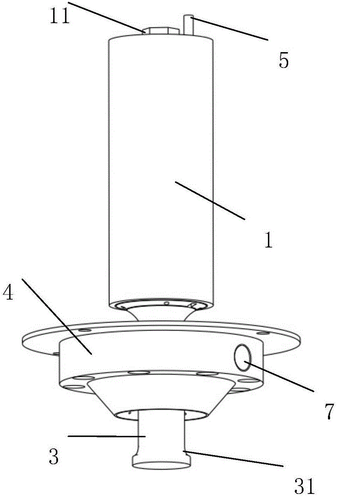
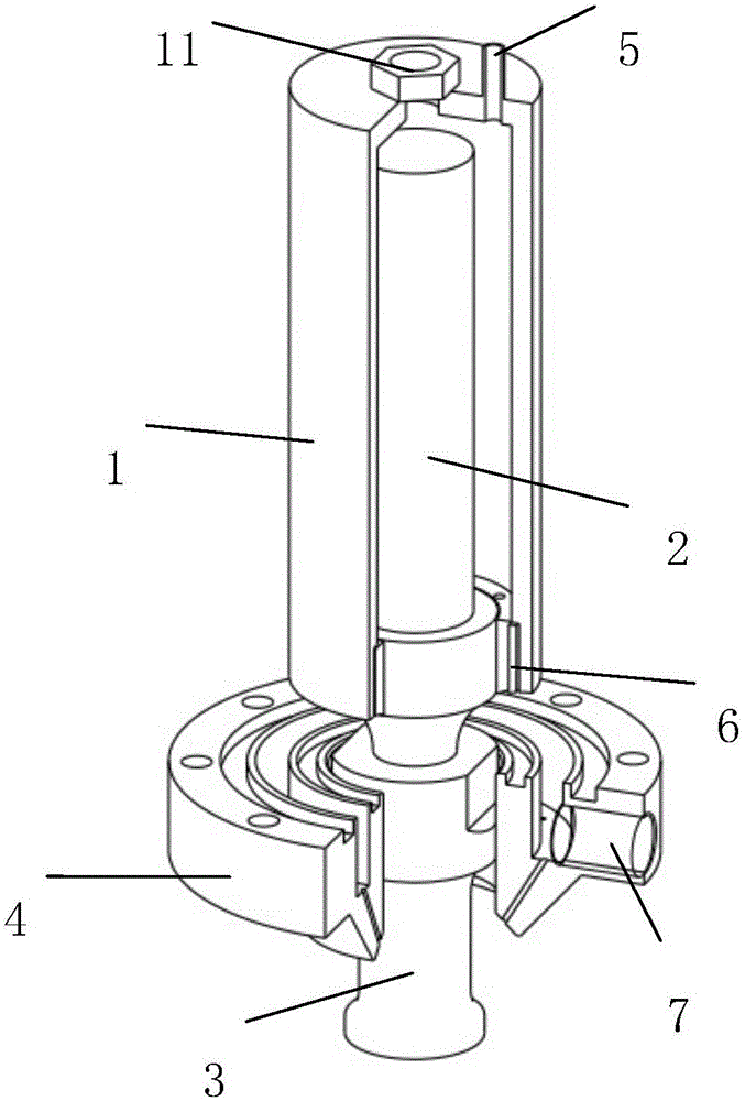
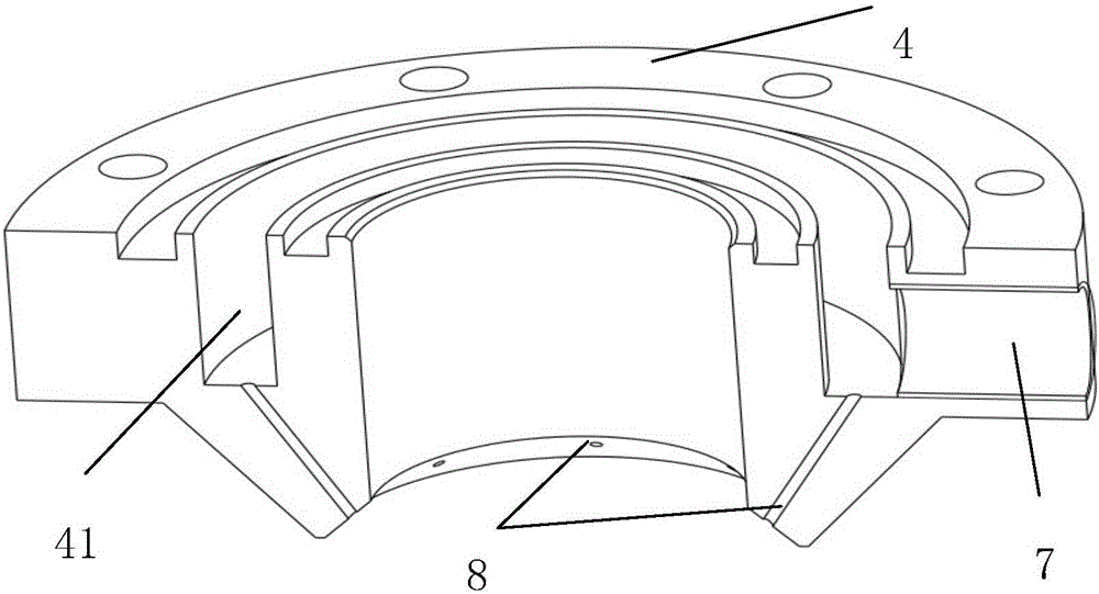
[0017] As shown in the figure, this ultrasonic atomization device for suspension is characterized in that it includes a transducer housing 1, a transducer 2, an atomization tool head 3, a liquid spray ring 4, and an air inlet 5. The air outlet hole 6, the liquid inlet hole 7 and the liquid outlet hole 8, the transducer housing 1 is covered on the outside of the transducer 2, and the transducer 2 is connected through the wire interface 11 at the top of the transducer housing 1 Ultrasonic power supply; the atomizing tool head 3 is connected to the transducer 2 through screws, and the transducer 2 passes through the central hole of the baffle and is snap-connected with the spray ring 4 . There is an air outlet 6 at the bottom of the transducer shell 1, and the gap between the transducer shell 1 and the transducer 2 is filled with heat-conducting glue; on the one hand, it is ...


PUM


Abstract

The invention discloses an ultrasonic atomization device used for suspension liquid. The ultrasonic atomization device comprises a transducer shell, a transducer, an atomization tool head, a liquid spraying ring, an air inlet hole, an air outlet hole, a liquid inlet and liquid outlet holes. The transducer shell wraps the transducer. The transducer is connected with an ultrasonic power supply through a wire interface located on the top of the transducer shell. The atomization tool head is connected with the transducer. The transducer is connected with the liquid spraying ring in a clamping and buckling mode. The air outlet hole is formed in the bottom of the transducer shell. A gap between the transducer shell and the transducer is filled with heat conducting glue. The air inlet hole is formed in the upper portion of the transducer shell. Compressed air enters the interior of the transducer shell through the air inlet hole, and flows rapidly in the transducer shell cavity. According to the ultrasonic atomization device, the atomization ability and atomization efficiency of the ultrasonic atomization device are improved, the atomization of the suspension liquid and a solution is achieved, in addition, the device is not limited by liquid storage and the liquid level and can work continuously, and the ultrasonic atomization device has wide application prospects in the field of thermal power plant flue gas desulfurization and denitration systems.

Description

technical field [0001] The invention relates to a liquid spraying device, in particular to an ultrasonic atomizing device for atomizing suspensions with high viscosity or containing tiny solid particles, especially suitable for flue gas desulfurization and denitrification systems in thermal power plants , belonging to the field of ultrasonic atomization. Background technique [0002] Sulfur dioxide is a gaseous pollutant with a large amount and a wide range of influence among the current air pollutants. With the rapid development of human society, the demand for energy continues unabated. This is doomed that the problem of environmental pollution will become increasingly severe, and power plants consume a lot of coal and produce a lot of sulfur dioxide, so desulfurization of power plants is an important means of protecting the environment. At present, most power plants use wet desulfurization process. The slurry produced in this process is sprayed out through the atomizin...

Claims


Application Information

Patent Timeline
IPC IPC(8): B05B17/06
CPCB05B17/06
Inventor 邱俭军刘宁杨帆邱贝赵崇安
Owner 杭州瑞利声电技术有限公司
Why Eureka
Try Eureka