Supporting roller surface deoiling system

A technology for supporting rollers and oil systems, which is applied in the directions of removing smoke and dust, keeping the roller equipment in an effective state, cleaning methods and appliances, etc. Oil effect, easy operation and maintenance, reliable action effect

Active Publication Date: 2017-04-26
CHINA NAT HEAVY MACHINERY RES INSTCO
View PDF5 Cites 8 Cited by
  • Summary
  • Abstract
  • Description
  • Claims
  • Application Information

AI Technical Summary

Problems solved by technology

Unable to block the rolling oil splashed in the frame
If it is not adjusted properly, the oil scraper 12 will also affect the quality of the roller surface, thereby affecting the surface quality of the strip

Method used


Image

  • Supporting roller surface deoiling system
  • Supporting roller surface deoiling system
  • Supporting roller surface deoiling system

Examples


Embodiment 1

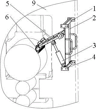
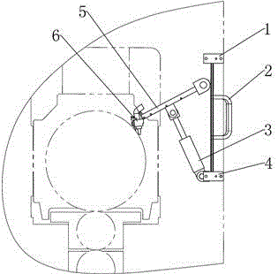
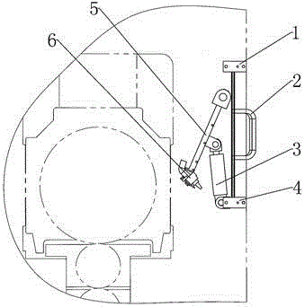
[0025] This embodiment provides a figure 1 The shown supporting roller surface degreasing system includes degreasing beam 6, oil retaining plate frame, swing oil cylinder 3, lower track beam 4, protective door 2 and upper track beam 1, and the upper track beam 1 and lower track beam 4 are both Horizontally fixed on the archway 9 on both sides of the frame, the end of the piston rod of the swing cylinder 3 is hinged on the lower surface of the oil deflector frame, and the cylinder body of the swing cylinder 3 is hinged on the lower track beam 4 through the hinge hole. The protective door 2 is arranged between the upper track beam 1 and the lower track beam 4 through a sliding connection, one end of the oil retaining plate frame is connected with the oil removal beam 6, the other end is hinged with the arches 9 on both sides of the frame, and the end is connected with the guard Door 2 connects.

[0026] Such as figure 1 As shown, the back-up roll surface degreasing system is i...

Embodiment 2

[0029] On the basis of Embodiment 1, this embodiment provides a backup roll surface oil removal system, the top of the oil deflector frame is provided with a plurality of inclined plates 10, and the plurality of inclined plates 10 are distributed in a herringbone shape , the joint of the oil retaining plate frame and the lower end of the swash plate 10 is provided with an oil drain hole.

[0030] Oil baffle frame 5 upper and lower all play the effect of oil baffle. A plurality of sloping plates 10 are distributed in a herringbone shape to guide the oil, and guide the oil dropped on the top of the oil baffle frame 5 to flow out through the oil drain holes on both sides. Because the oil baffle frame 5 is hinged with the archways 9 on both sides of the frame, the width is greater than the width of the plate, and the rolling oil flows to the both sides of the plate through the drain hole, and can not fall on the plate. The structure of the oil baffle frame 5 is as Figure 4 show...

Embodiment 3

[0032] On the basis of Embodiment 1, this embodiment provides a backup roll surface degreasing system. The degreasing beam 6 includes a beam, a pressure plate 11, an elastic oil scraper 12, an air knife 7, and is arranged at equal intervals along the beam. A plurality of short air intake pipes 8, one end of the beam is provided with a mounting plate 15 connected to the oil deflector frame, and the other end is provided with a pressure plate 11, and the elastic oil scraper 12 is arranged between the pressure plate 11 and the end surface of the beam , the air knife 7 is arranged on the lower end surface of the beam, the short air inlet pipe 8 is arranged on the top surface of the beam and communicates with the air knife 7, and the short air inlet pipe 8 is connected to the compressed air pipeline. The structure of degreasing beam 6 is as Figure 5 shown.

[0033] The compressed air blown out by the oil removal beam 6 through the short intake pipe 8 blocks most of the rolling oi...


PUM


Abstract

The invention provides a supporting roller surface deoiling system which comprises a deoiling cross beam, an oil blocking plate frame, a swinging oil cylinder, a lower track beam, a protective door and an upper track beam. The upper track beam and the lower track beam are horizontally and fixedly arranged on a memorial archway located on the two sides of a rack. The end of a piston rod of the swinging oil cylinder is hinged to the lower surface of the oil blocking plate frame. A cylinder block of the swinging oil cylinder is hinged to the lower track beam through a hinge hole. The protective door is slidably connected between the upper track beam and the lower track beam. One end of the oil blocking plate frame is connected with the deoiling cross beam, and the other end of the oil blocking plate frame is hinged to the memorial archway on the two sides of the rack and connected with the protective door. According to the supporting roller surface deoiling system, an airtight space is formed through the oil blocking plate frame, the roller, rolling pieces and the protective door, rolling oil splashing in the rack can be blocked, it is guaranteed that the blocked rolling oil is sealed on the rolling inlet side, and the surrounding environment of a rolling mill is not polluted; and the stretching and retracting positions of the swinging oil cylinder determine the two working positions of the oil blocking plate frame, and free switching between a deoiling state and a roller changing state is achieved.

Description

technical field [0001] The invention belongs to the technical field of cold-rolled plate and strip equipment, and in particular relates to a support roll surface degreasing system. Background technique [0002] During the cold rolling process of the plate and strip, it is necessary to spray emulsion or rolling oil on the roll gap and the roll body to lubricate the roll gap and cool the roll. Due to the high viscosity of the rolling oil, the rolling oil sprayed on the rolling entrance side will Adhering to the surface of the roll, the rolling oil adhering to the roll surface will be brought to the rolling exit side through the rotation of the roll, causing a large amount of rolling oil to fall on the plate surface, causing great damage to the degreasing at the exit side The difficulty, especially for four-high mills, is aggravated by the rotation direction of the back-up rolls. [0003] The existing device mainly uses an oil scraper to scrape off the oil on the roller surfac...

Claims


Application Information

Patent Timeline
Patent Type & Authority Applications(China)
IPC IPC(8): B21B28/00B08B1/02B08B15/04
CPCB08B1/005B08B1/02B08B15/04B21B28/00
Inventor 苏旭涛徐利璞刘云飞计江谢磊
Owner CHINA NAT HEAVY MACHINERY RES INSTCO
Why Eureka
Try Eureka