
Blade powder blank molding device and molding method for injection powder filler

A molding device and spray technology, which are applied in the directions of transportation and packaging, conveying bulk materials, conveyors, etc., can solve the problems of long production cycle and high cost, and achieve the effects of convenient operation, solving product deformation and simple structure.

Active Publication Date: 2018-12-28
ZHUZHOU CEMENTED CARBIDE CUTTING TOOLS CO LTD
View PDF1 Cites 0 Cited by
  • Summary
  • Abstract
  • Description
  • Claims
  • Application Information

AI Technical Summary

Problems solved by technology

In addition, this method is only applicable to some specific products such as products with symmetrical groove structure, such as cutting knives, A series products, etc.
At the same time, due to the change of product size, the corresponding mold fixture and push shoe need to be remade, so the cost is high and the production cycle is long

Method used


Image

  • Blade powder blank molding device and molding method for injection powder filler
  • Blade powder blank molding device and molding method for injection powder filler
  • Blade powder blank molding device and molding method for injection powder filler

Examples


Embodiment Construction

[0035] The present invention will be further described in detail below in conjunction with the accompanying drawings and specific embodiments.

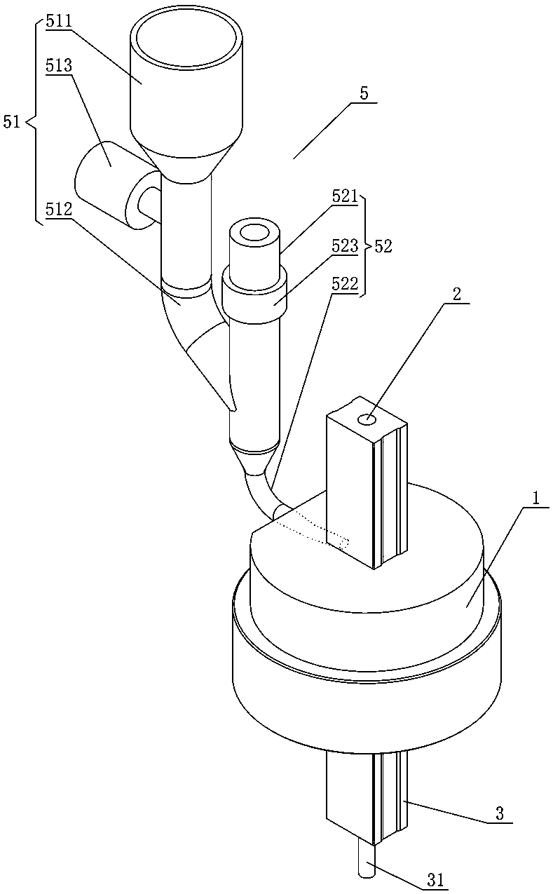
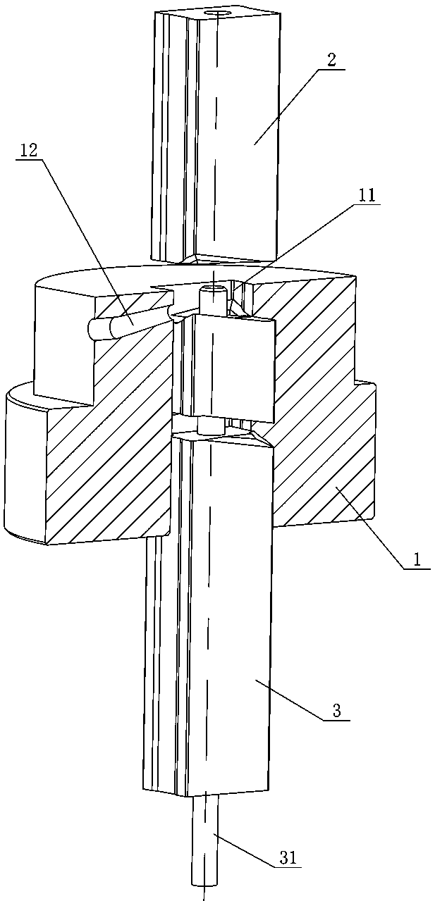
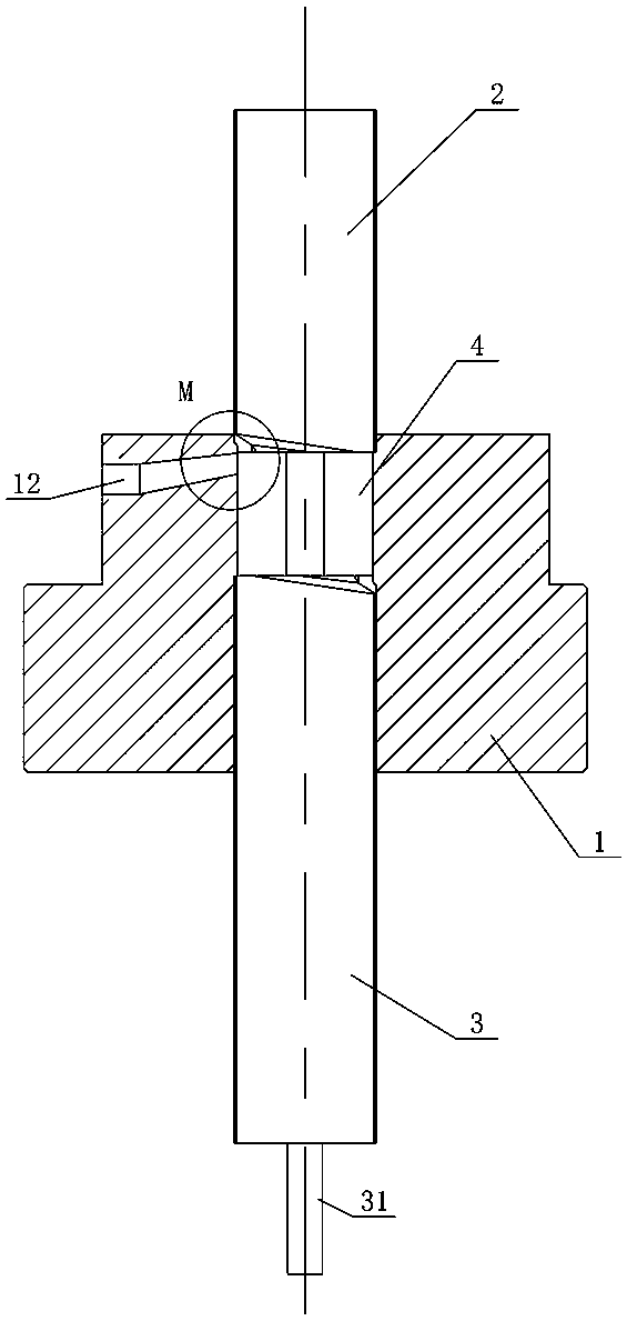
[0036] Figure 1 to Figure 6 It shows an embodiment of the blade blank molding device of the spray powder filler of the present invention, which includes a mold body 1, and a through cavity 11 is opened on the mold body 1, and the top and bottom of the mold body 1 are respectively provided with extending molds. The punch 2 and the ejector 3 in the cavity 11, the powder filling area 4 is formed between the bottom groove surface of the punch 2, the top groove surface of the ejector 3 and the cavity 11, and the powder filling area 4 is formed on the side of the mold body 1. The powder injection channel 12 communicated with the filling area 4, and the powder injection part 5 communicated with it is installed outside the powder injection channel 12. When in use, the punch 2 and the ejector 3 are directly inserted into the cavity 11 and a ...


PUM


Abstract

The invention discloses a blade powder blank forming device and method adopting spray type powder filling. The blade powder blank forming device adopting spray type powder filling comprises a mold body. The mold body is provided with a through cavity. The top and bottom of the mold body are provided with a punch pin and an ejector correspondingly, wherein the punch pin and the ejector extend into the cavity. A bottom groove profile surface of the punch pin, a top groove profile surface of the ejector and the cavity define a powder filling area. The side portion of the mold body is provided with a powder spray channel communicating with the powder filling area, and a powder spraying component is arranged on the outer portion of the powder spray channel and communicates with the powder spray channel. The blade powder blank forming method adopting spray tube powder filling is performed through the blade powder blank forming device adopting spray tube powder filling and comprises the following steps of S1 conducting installation, S2 arranging a powder filling area, S3 conducting spray type powder filling, S4 closing the powder spray channel, S5 conducting compression molding, S6 taking out a piece and S7 keeping the steps from the step S2 to the step S6 being circularly executed. The blade powder blank forming device and method adopting spray type powder filling have the advantages that the structure is simple, operation is easy and convenient, the application range is wide, and it can be guaranteed that the compression ratios of all areas can be identical in the powder forming process.

Description

technical field [0001] The invention mainly relates to the field of solid powder compression molding dies, in particular to a blade blank molding device and molding method for injection powder filler. Background technique [0002] At present, the powder filling adopts the volumetric method, that is, the pusher shoe moves back and forth on the top surface of the mold body, and the mold cavity is filled by the gravity of the powder itself. After the powder is filled, the bottom of the powder in the mold cavity has a groove structure that is consistent with the surface of the ejector. Similar shape, but the top surface of the powder is level with the top surface of the cavity. With the development of tungsten carbide CNC inserts, complex insert structures are constantly emerging, the groove structure of the top and bottom of the insert is becoming more and more complex and the height of the groove is gradually increasing, so the existing filling pressing method is adopted, beca...

Claims


Application Information

Patent Timeline
Patent Type & Authority Patents(China)
IPC IPC(8): B22F3/03B22F5/00B65G53/50
CPCB22F3/03B22F5/00B22F2005/001B65G53/50
Inventor 袁彩云张京赵丽丽冯文
Owner ZHUZHOU CEMENTED CARBIDE CUTTING TOOLS CO LTD
Learn More