Rotating disk platform type steel structure assembly device

An assembly equipment, platform-type technology, applied in metal processing equipment, metal processing, manufacturing tools, etc., can solve problems such as difficulty in ensuring accuracy and product quality, and achieve improved flexibility, reduced risk of electric shock, and good versatility. Effect

Active Publication Date: 2017-04-26
青岛嘉和鑫钢铁有限公司
View PDF6 Cites 12 Cited by
  • Summary
  • Abstract
  • Description
  • Claims
  • Application Information

AI Technical Summary

Problems solved by technology

In the workshop of the prior art, there is usually no special equipment for this kind of operation, and it is usually assembled on the spot in the workshop, so it is difficult to guarantee the accuracy and product quality

Method used


Image

  • Rotating disk platform type steel structure assembly device
  • Rotating disk platform type steel structure assembly device
  • Rotating disk platform type steel structure assembly device

Examples


Embodiment 1

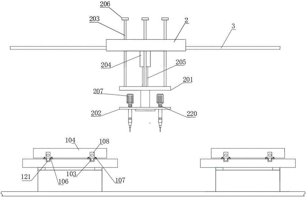
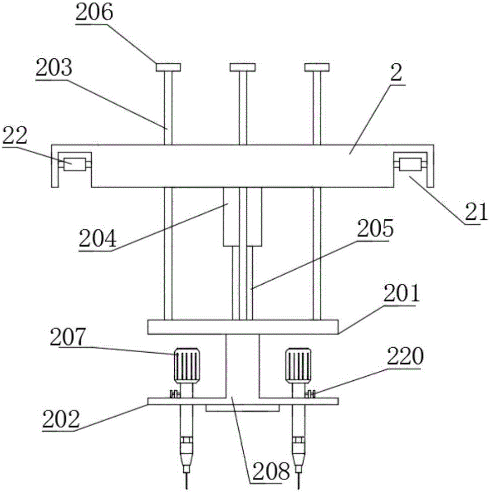
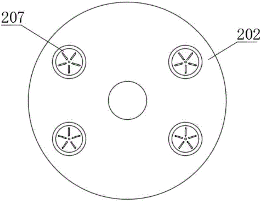
[0017] like Figure 1-6 As shown, this embodiment provides a turntable platform-type steel structure assembly equipment, including an operating platform, an assembly device, and a suspension rail; the suspension rail includes two parallel steel rails 3; the steel rails 3 are installed on a bracket or a wall Above; the assembly device includes a mounting plate 2, an upper mounting plate 201, a rotating plate 202, a sliding rod 203, a lifting column 204 and an electric screwdriver 207; the two ends of the bottom of the mounting plate 2 are respectively provided with upper concave chute 21 The chute 21 is provided with a plurality of rollers 22; the rollers 22 are movable and fixed on the side wall of the chute 21 through the wheel shaft; the assembly device is installed on the rail 3 through the rollers 22 on the mounting plate 2; The lifting column 204 is fixed on the bottom of the mounting plate 2, and its piston rod 205 is connected to the upper mounting plate 201; The lower...

Embodiment 2

[0019] like Figure 1-6 As shown, this embodiment provides a kind of steel structure assembly equipment. What is different from Embodiment 1 is that the operating platform includes slide rails and two clamping platforms movably installed on the slide rails; the clamping platform includes Base 101, table top 102 and two clamping mechanisms; the bottom of the base 101 is provided with a chute 111; it is installed on the slide rail through the chute 111; the table top 102 is arranged on the top of the base 101, the upper surface of the table top 102 There are two slideways 121 arranged in parallel, the cross-section of the slideway 121 is a convex structure, perpendicular to the direction of the slideway; two clamping mechanisms are arranged oppositely, and the clamping mechanism includes two sliders 103 , a bar splint 104 and a positioning bolt 107; the two sliders 103 are slidably installed in two slideways 121 respectively, and the cross section of the slider 103 is an I-shape...


PUM


Abstract

The invention provides a steel structure assembly device. The steel structure assembly device comprises an operating platform, an assembly device and hoisting rails; the assembly device is movably installed on the hoisting rails through rolling wheels; a lifting column is fixed to the bottom of an installing plate, and a piston rod of the lifting column is connected with an upper installing disk; the upper portion of a sliding rod is movably installed on a movable plate through a sliding hole formed in the installing plate; the lower portion of the sliding rod is fixedly connected with the upper installing disk; a limiting block is arranged on the top of the sliding rod; a connecting column is arranged at the bottom of the upper installing disk; a horizontal disk is arranged at the bottom of the connecting column and is provided with an annular slide rail; a rotating disk is of an annular structure and is movably installed on the annular slide rail of the horizontal disk through an annular groove in the bottom; an electric screw driver comprises a motor, a shell and a screw driver blade; the motor is connected with a power source through a controller; the screw driver blade is connected with a motor shaft of the motor through a speed reducing box which is arranged in the shell; the electric screw driver is installed on an installing hole of the rotating disk through the shell; and the operating platform is arranged below the assembly device.

Description

technical field [0001] The invention relates to the technical field of steel structure processing, in particular to a turntable platform steel structure assembly equipment. Background technique [0002] The steel structure is a kind of basic component made of section steel or steel plate, according to the requirements of use, through welding or bolt connection, etc., according to a certain law to form a load-bearing mechanism. Steel structures are widely used in various engineering constructions, such as steel bridges, steel workshops, steel gates, various large pipeline containers, high-rise buildings and tower rail mechanisms, etc. Due to the comprehensive advantages of light weight, easy installation, short construction period, good seismic performance, fast investment recovery and less environmental pollution, the steel structure system has been widely used in the construction industry. In order to improve the assembly efficiency of the steel structure and speed up the ...

Claims


Application Information

Patent Timeline
Patent Type & Authority Applications(China)
IPC IPC(8): B23P19/00B23P19/06
CPCB23P19/00B23P19/069
Inventor 张振海
Owner 青岛嘉和鑫钢铁有限公司
Why Eureka
Try Eureka