
A Lubricated Round Knife Die Cutting Fixture

A technology of circular knife mold and circular knife, which is applied in metal processing and other directions, can solve the problems of adhesive back-adhesion, glue overflow, glue sticking knife, etc., and achieve the effect of simple operation, uniform lubrication and high cutting efficiency

Active Publication Date: 2018-02-27
青岛盈科精密橡塑有限公司
View PDF8 Cites 0 Cited by
  • Summary
  • Abstract
  • Description
  • Claims
  • Application Information

AI Technical Summary

Problems solved by technology

[0003] The purpose of the present invention is to overcome the shortcomings of the prior art, solve the problems of glue sticking to the knife, adhesive sticking back, glue overflow and deformation during the die-cutting molding process of the polymer tape, and seek to design a lubricated round knife die-cutting fixture

Method used


Image

  • A Lubricated Round Knife Die Cutting Fixture

Examples


Embodiment 1

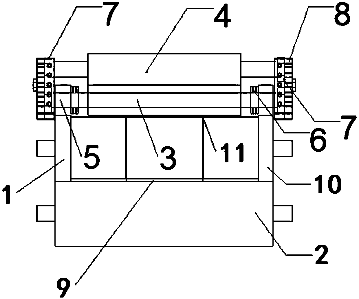
[0010] The main structure of the lubricated round knife die-cutting fixture involved in this implementation includes a round knife 1, a steel shaft 2, a rubber shaft 3, a sponge shaft 4, a limit ring 5, a positioning ring 6, a bearing 7, a slot 8, and a base 9 , knife edge 10 and knife pillow 11; The top of the matrix 9 of rectangular inner hollow structure is provided with the round knife 1 of cylindrical structure, and the periphery of round knife 1 is provided with the knife edge 10 of blade-like structure, and the left and right ends of round knife 1 are all A knife pillow 11 with a circular structure is provided, and the circular knife 1 is fixedly connected with the base body 9 through the knife pillow 11. The lower part of the base body 9 is provided with a steel shaft 2 with a cylindrical structure, and the top of the base body 9 is provided with a rubber shaft with a cylindrical structure. 3 and the sponge shaft 4, the rubber shaft 3 of the rubber-encapsulated structur...


PUM


Abstract

The invention belongs to the technical field of mechanical jig equipment, and relates to a lubricating type circular-knife die cutting jig. The main body structure of the lubricating type circular-knife die cutting jig comprises a circular knife, a steel shaft, a rubber shaft, a sponge shaft, limiting rings, positioning rings, bearings, clamping grooves, a base body, a knife point and knife rests; the circular knife is arranged on the upper part of the base body; the knife point is arranged on the periphery of the circular knife; the knife rests are arranged on the left end and the right end of the circular knife respectively; the circular knife is fixedly connected to the base body through the knife rests; the steel shaft is arranged at the lower part of the base body; the rubber shaft and the sponge shaft are arranged at the top of the base body, wherein the rubber shaft and the sponge shaft are of cylindrical structures, the rubber shaft of a rubber coating type structure is arranged at the lower part, and the rubber shaft is arranged at the upper part; the left end and the right end of the rubber shaft are connected to the left end and the right end of the sponge shaft respectively through the bearings and the clamping grooves; and the limiting rings and the positioning rings are arranged at the positions, located on the inner sides of the bearings, of the left end and the right end of the rubber shaft respectively, wherein the limiting rings and the positioning rings are of circular ring structures. The lubricating type circular-knife die cutting jig is simple in structure, reliable in principle, novel in design, simple and convenient to operate, wide in application range, friendly to use environment, good in cutting effect and high in cutting efficiency.

Description

Technical field: [0001] The invention belongs to the technical field of mechanical jig equipment, and relates to a lubricating round knife die-cutting jig, which is used to assist in the production of polymer adhesive tapes, and to avoid glue sticking to the knife, adhesive sticking back and glue in the process of die-cutting and molding production and processing. spillover phenomenon. Background technique: [0002] Polymer tapes used to bond components of electronic products are developing in the direction of diversification and specialization with the development of the electronics industry. The adhesives on polymer tapes are becoming thinner, more fluid and thicker. It is also getting bigger and bigger; the die-cutting method of die-to-glue in the prior art is troubled by sticking knife, adhesive back-adhesion and glue overflow, which leads to the bad situation of glue deformation and glue overflow, and even cannot produce and process polymers. Polymer tape, this problem...

Claims


Application Information

Patent Timeline
Patent Type & Authority Patents(China)
IPC IPC(8): B26F1/38B26F1/44B26D7/08B26D7/26
CPCB26D7/088B26D7/2621B26F1/38B26F1/44
Inventor 陈涛欧阳宝旭
Owner 青岛盈科精密橡塑有限公司
Learn More