A disc mixer
A mixer and disc-type technology, which is applied in the field of polymer blending equipment, can solve the problem of not being suitable for melting, plasticizing, mixing and extrusion of polymer-based materials, limiting screw speed and increasing output, and not considering material space Sealing and other issues, to achieve the effect of easy disassembly and cleaning, increased discharge performance, and simple structure
- Summary
- Abstract
- Description
- Claims
- Application Information
AI Technical Summary
Problems solved by technology
Method used
Image
Examples
Embodiment 1
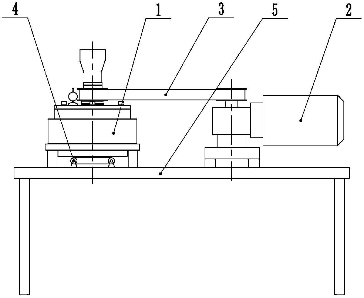
[0082] Such as figure 1 As shown, a disc mixer of the present invention includes a mixer main body 1, a power system 2, a transmission component 3, a strip conveying device 4 and a frame 5; wherein the transmission component 3 transmits the power provided by the power system 2 Give mixer body 1. The mixer main body 1 and the power system 2 are mounted on the frame 5 . The strip conveying device 4 is located below the mixer main body 1 and installed on the frame 5 .
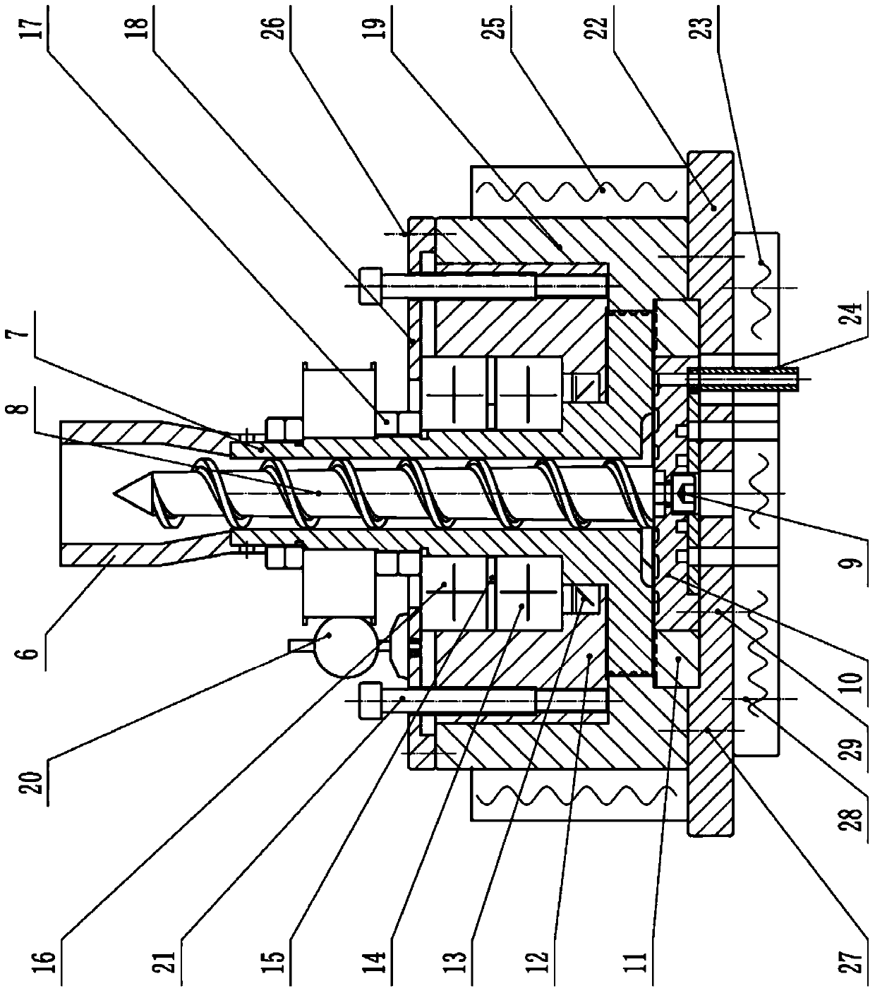
[0083] Such as figure 2 Shown, the mixer main body 1 in a kind of disc type mixer of the present invention (serial number sees figure 1 ) connection and installation relations are as follows:
[0084] A screw rod 8 is sleeved in the rotating body 7 of the moving disk, and the screw rod 8 is fixed on the fixed disk 10 through the screw rod mounting screw 9 . The fixed plate 10 is covered with a fixed plate return ring 11 . A bearing housing 12 , a seal 13 , a bearing 14 , a spacer ring 15 , a bearing 2 16 , ...
Embodiment 2
[0098] Such as figure 2 As shown, in order to accurately adjust the gap between the end surface of the rotating body 7 of the moving disk and the upper surface of the fixed disk 10 to meet the processing requirements of different materials, the main body of the present invention also includes a gap adjustment device. In the following, this embodiment will describe in detail the composition of the gap adjustment device and the specific working process of the gap adjustment.
[0099] First, the gap adjustment device includes a depth gauge 20 and a gap adjustment bolt 21 . In the present invention and the embodiment, the locking of the bearing lock nut 17 makes the rotor 7, the bearing housing 12, the seal 13, the first bearing 14, the spacer ring 15, and the second bearing 16 integrated. The specific gap adjustment process is as follows:
[0100] Before the gland mounting screw 26 is tightened, use the gap adjustment bolt 21 to adjust the gap between the end surface of the ro...
Embodiment 3
[0103] The present invention can also adjust the gap between the end surface of the rotor rotating body and the upper end surface of the fixed disk by adding gaskets, and the specific implementation is as in the present invention and the embodiments Figure 9 shown.
[0104] Specifically, the method of increasing the gasket 51 is used to adjust the rotating disc rotating body 7 (serial number is the same as figure 2 ) end face and fixed plate 10 (serial number is the same as figure 2 ) gap between the upper end faces, the specific process is:
[0105] Place some spacers on the machine barrel 19 (serial number is the same as figure 2 ) and bearing housing 12 (the same serial number figure 2 ) between the bosses, as the number and height of the gaskets increase, the bearing housing 12 (serial number is the same as figure 2 ) to rise upwards to drive the moving plate rotating body 7 (serial number is the same as figure 2 ) and the parts on it rise as a whole, and the m...
PUM
| Property | Measurement | Unit |
|---|---|---|
| melt flow index | aaaaa | aaaaa |
| density | aaaaa | aaaaa |
| density | aaaaa | aaaaa |
Abstract
Description
Claims
Application Information
 - R&D
- Intellectual Property
- Life Sciences
- Materials
- Tech Scout
- Unparalleled Data Quality
- Higher Quality Content
- 60% Fewer Hallucinations
Browse by: Latest US Patents, China's latest patents, Technical Efficacy Thesaurus, Application Domain, Technology Topic, Popular Technical Reports.
© 2025 PatSnap. All rights reserved.Legal|Privacy policy|Modern Slavery Act Transparency Statement|Sitemap|About US| Contact US: help@patsnap.com


