Double-drive counterweight high-speed stacking machine

A stacker and counterweight technology, applied in the field of warehousing and logistics equipment, can solve the problem of affecting the fork device to grab, transport and stacking access to goods, increase the loss of the power wheel and the friction motor of the track, and the running accuracy of the cargo platform. Stability reduction and other problems, to achieve the effect of high repeated positioning accuracy, improved service life, improved operation accuracy and stability

Pending Publication Date: 2017-04-26
TAIYUAN OTTLE LOGISTICS TECH CO LTD
View PDF5 Cites 7 Cited by
  • Summary
  • Abstract
  • Description
  • Claims
  • Application Information

AI Technical Summary

Problems solved by technology

[0002] It has been about 20 years since the domestic stacker was developed in the 1980s. The models, specifications, equipment performance and product quality have gradually approached those of the same type of stacker abroad. Technical performance and various parameters, but there are still some problems; the ordinary column stacker cargo platform usually uses guide wheels as the guide tool during the lifting process, and the guide wheels need to leave a large gap during the installation process. The guide wheels on both sides of the platform often experience different degrees of local wear due to uneven force during operation, resulting in the reduction of the operating accuracy and stability of the loading platform with time, which in turn affects the grabbing, handling and handling of the fork device. Stacking or accessing goods from upper racks
Ordinary stackers consume more energy than counterweight stackers, but counterweight type stackers are difficult to install and maintain
Ordinary walking high-speed stacker consists of two power wheels, that is, one motor at the front and the rear drives one power wheel. If the speed of the two motors is not synchronized in this transmission arrangement, the speed of the two power wheels will be different, and the speed will increase during the process. The friction between the power wheel and the track and the loss of the motor

Method used


Image

  • Double-drive counterweight high-speed stacking machine
  • Double-drive counterweight high-speed stacking machine
  • Double-drive counterweight high-speed stacking machine

Examples


Embodiment Construction

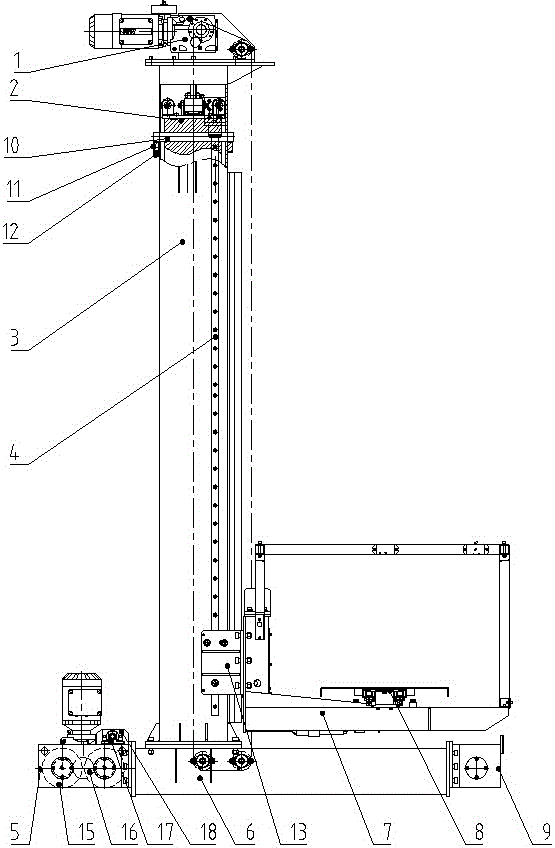
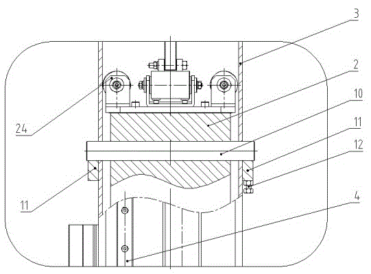
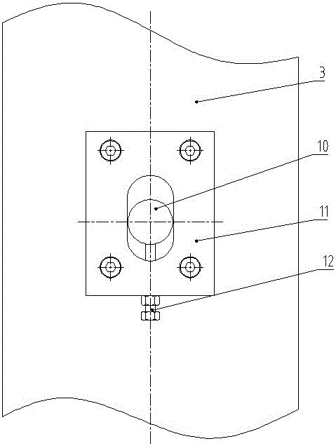
[0013] The lower beam 6 is as the base of the stacker, and the active wheel box earrings 17 and the lower beam earrings 18 in the lower beam 6 are hinged together with pins in the active walking system 5 . Passive walking system 9 is installed on the passive wheel box mounting plate of lower beam 6. The lower flange of the column in the column 3 is connected with the column mounting plate of the lower beam 6, the linear guide rail 4 is installed on both sides of the column 3, the slider 13 in the linear guide rail 4 is connected with the slider mounting plate in the loading platform 7, and the fork 8 Installed on the loading platform 7, the counterweight 2 is installed in the column 3, and the lifting system 1 is connected to the upper flange of the column 3; Installed on the column 3, the adjusting bolt 12 is installed on the fixed block 11, and the pin shaft 10 passes through the fixed block 11 and the counterweight 2 to connect the two together. Driving wheel box 14, walki...


PUM


Abstract

The invention discloses a double-drive counterweight high-speed stacking machine, and aims to reduce energy consumption and facilitate mounting and maintenance of a counterweight. The double-drive counterweight high-speed stacking machine comprises a lifting system, the counterweight, a counterweight adjusting device, an upright post, linear guide rails, a sliding block, a lower cross beam, a cargo carrying table, a fork, an active travelling system and a driven travelling system, wherein the lifting system comprises a lifting gear motor, a synchronous belt, synchronous pulleys and a lifting bracket; the synchronous pulleys mesh with the synchronous belt; the linear guide rails are mounted on the two sides of the upright post; the active travelling system comprises a driving wheel box, a gear drive wheel train, travelling wheels and a travelling gear motor; the travelling wheels and the gear drive wheel train are mounted in the driving wheel box; the driven travelling system comprises a driven wheel box and driven wheels; the driven wheels are mounted in the driven wheel box; a lower cross beam hinge lug ring, an upright post mounting plate and a driven wheel box mounting plate are arranged on the lower cross beam; the counterweight adjusting device comprises a hinge pin, a fixed block and an adjusting bolt; the fixed block is mounted on the upright post of the stacking machine; and the hinge pin is connected with the fixed block and the counterweight.

Description

technical field [0001] The invention relates to warehousing and logistics equipment, in particular to a high-speed stacker which uses a fork device to grab, carry and stack or access unit goods from high-rise shelves. Background technique [0002] It has been about 20 years since the domestic stacker was developed in the 1980s, and the models, specifications, equipment performance and product quality have gradually approached those of the same type of stacker abroad. Technical performance and various parameters, but there are still some problems; the ordinary column stacker cargo platform usually uses guide wheels as the guide tool during the lifting process, and the guide wheels need to leave a large gap during the installation process. The guide wheels on both sides of the platform often experience different degrees of local wear due to uneven force during operation, resulting in the reduction of the operating accuracy and stability of the loading platform with time, whi...

Claims


Application Information

Patent Timeline
Patent Type & Authority Applications(China)
IPC IPC(8): B66F9/07B66F9/12
CPCB66F9/07B66F9/072B66F9/12
Inventor 王磊韩二占田李川徐腾飞成燕燕范晓亮
Owner TAIYUAN OTTLE LOGISTICS TECH CO LTD
Why Eureka
Try Eureka