High-precision embedded part reinforcing and mounting device and method and purpose

A technology for installing devices and embedded parts, which is applied in the fields of construction, building structure, and building materials, and can solve problems such as the inability to meet the high-precision installation and construction requirements of embedded parts, affecting the fixed state, and damage to embedded parts. Achieve good application effect, improve installation efficiency, and easy construction and operation

Active Publication Date: 2017-04-26
CHINA NUCLEAR IND 24 CONSTR
View PDF8 Cites 6 Cited by
  • Summary
  • Abstract
  • Description
  • Claims
  • Application Information

AI Technical Summary

Problems solved by technology

[0004] The technical problem to be solved by the present invention is that the embedded parts installed in the construction of the existing nuclear power plant are easy to cause damage to the embedded parts themselves when they are buried, thereby affecting the fixed state and causing construction difficulties. Therefore, a high-precision embedded part is designed. Reinforced installation device, method, and use, which connect multiple embedded parts into an embedded part fixing unit to form a whole, and can install and adjust the entire embedded part, compared with the installation and adjustment of a single embedded part method, the installation speed is fast, and the construction operation is simple, which greatly improves the installation efficiency of embedded parts and solves the problem that the existing embedded parts reinforcement technology cannot meet the high-precision installation and construction requirements of embedded parts

Method used


Image

  • High-precision embedded part reinforcing and mounting device and method and purpose
  • High-precision embedded part reinforcing and mounting device and method and purpose

Examples


Embodiment

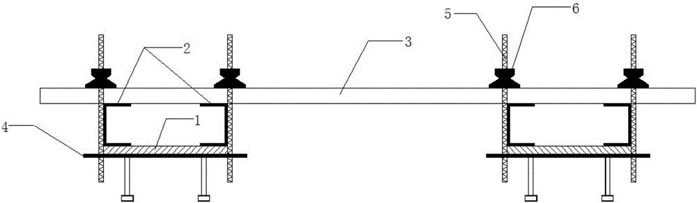
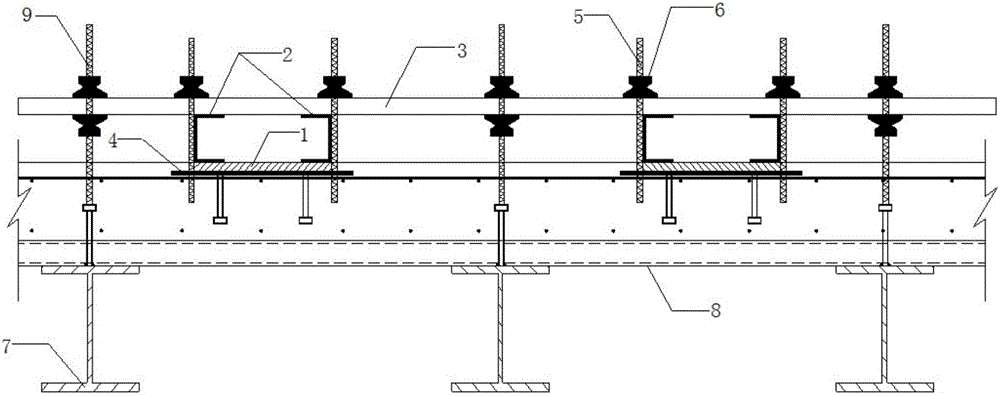
[0022] Such as figure 1 , figure 2 As shown, a high-precision embedded parts reinforcement installation device is first assembled into a figure 1 The fixed unit, the fixed unit is mainly composed of a supporting device, a connecting device, a limiting device, a locking device and a pressing device, wherein the limiting device is preferably two pull screws 5, and the connecting device is preferably two For steel pipes 3 parallel to each other, the supporting device is preferably two pieces of channel steel 2 , the locking device is preferably a wing nut 6 , and the supporting device is preferably a steel bar 4 . The specific installation method is as follows:

[0023] (1) Configure the embedded part fixing unit: set two symmetrical channel steels 2 above each embedded part 1, set steel bars 4 under the embedded part 1 for support, set the steel pipe above the channel steel 2, channel steel 2 and The embedded parts 1 are arranged between two opposite pull screws 5, and the t...


PUM


Abstract

The invention discloses a high-precision embedded part reinforcing and mounting device and method and a purpose. The high-precision embedded part reinforcing and mounting device comprises fixing units which are connected with one another. Each fixing unit is mainly composed of a supporting device, a connecting device, a limiting device, a locking device and a pressing device. The connecting devices in the fixing units are connected. The supporting devices are arranged below embedded parts. The pressing device and the connecting devices are arranged above the embedded parts. The pressing devices are arranged between the embedded parts and the connecting devices. The limiting devices are fixed to the supporting devices after penetrating through the connecting devices. The locking devices are arranged above the connecting devices and arranged on the limiting devices in a sleeving mode. The multiple embedded parts are connected into an integral embedded part fixing unit, and the embedded parts can be mounted and adjusted integrally; and compared with a method for mounting and adjusting the embedded parts independently, the mounting speed is high, construction operation is easy and convenient, the mounting efficiency of the embedded parts is greatly improved, and the problem that an existing embedded reinforcing technique cannot meet the requirements for high-precision mounting and construction of the embedded parts is solved.

Description

technical field [0001] The invention belongs to the technical field of building construction, and in particular relates to a device, method and application for reinforcing and installing high-precision embedded parts. Background technique [0002] In nuclear power plants, embedded parts for the subsequent installation of electrical panels need to be installed on the floor, which are widely distributed, large in number, and high in density. The positioning accuracy of such embedded parts is required to be very high. Since the profiled steel plate concrete slab is thin, with a thickness of 203 mm, the embedded parts have a large aspect ratio, the slab surface is thin, and the rigidity is small. Considering the thickness of the concrete slab, the reinforcement measures for the embedded parts are limited, and the subsequent concrete work Disturbance to embedded parts will affect the accuracy of embedded parts. In order to ensure that the installation accuracy of the embedded pa...

Claims


Application Information

Patent Timeline
IPC IPC(8): E04B1/41E04G21/00
CPCE04B1/41E04G21/00
Inventor 陈明赵永秦体东张炳畅范庆华卓勇刘德才
Owner CHINA NUCLEAR IND 24 CONSTR
Why Eureka
Try Eureka