
Totally-enclosed high-pressure shallow plug drilling device and application method thereof

A fully enclosed, shallow layer technology, applied in the direction of earthwork drilling, wellbore/well components, etc., can solve the problems of high transportation and relocation costs, increased production costs, high equipment costs, etc., to achieve significant economic benefits, safe and reliable work, The effect of reducing production costs

Active Publication Date: 2017-04-26
中石化石油工程技术服务有限公司 +2
View PDF13 Cites 2 Cited by
  • Summary
  • Abstract
  • Description
  • Claims
  • Application Information

AI Technical Summary

Problems solved by technology

Its operating equipment is mainly composed of operating power equipment, derrick, blowout prevention pipe string, injection head, hydraulic control and other equipment and auxiliary devices; its main defect is that these equipments are high in cost, complex in structure, huge in equipment, and high in transportation and moving costs , the operating cost is also high, and there are many operating personnel that need to be configured. For example, a set of independent pressurized operating equipment and coiled tubing operating equipment, the price of a set is as high as 30-40 million yuan, which greatly increases the production cost.

Method used


Image

  • Totally-enclosed high-pressure shallow plug drilling device and application method thereof
  • Totally-enclosed high-pressure shallow plug drilling device and application method thereof
  • Totally-enclosed high-pressure shallow plug drilling device and application method thereof

Examples


Embodiment Construction

[0022] The present invention will be described in detail below in conjunction with the accompanying drawings, not to limit the protection scope of the present invention, and all improvements obtained by using the design idea of ​​the present invention belong to the protection scope of the present invention.

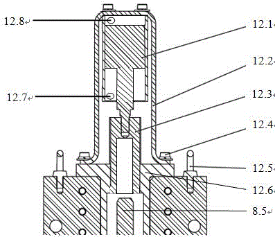
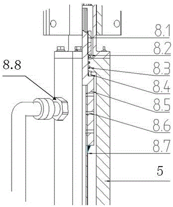
[0023] see figure 1 , the high-pressure shallow fully-enclosed drilling plug device includes a blowout preventer 5, the pipe body of the blowout preventer 5 is provided with a lower pressure port 3, and the inside of the pipe body is equipped with a piston assembly 7, and the upper end of the blowout preventer 5 is sequentially arranged from bottom to top It is connected with the upper pressure flange assembly 8 and the anti-rotation assembly 12, and the lower end is connected with the conversion sub-joint 2 and the anti-blowout sub-joint 1 sequentially from top to bottom, and the cylinder 12.1 in the anti-rotation assembly 12 passes through the spline sleeve 12.3 It is c...


PUM


Abstract

The invention belongs to the field of the oil industry, and discloses a totally-enclosed high-pressure shallow plug drilling device suitable for drilling and removing cement plugs in a shallow position close to a wellhead in an oil-gas water well and an application method thereof. A lower pressurizing port is formed in a pipe body of a blowout prevention pipe of the device, and a piston assembly is installed in the pipe body. The upper end of the blowout prevention pipe is connected with an upper pressurizing flange assembly and a rotation prevention assembly sequentially from bottom to top, and the lower end of the blowout prevention pipe is connected with a short conversion section and a short blowout prevention section sequentially from top to bottom. An air cylinder in the rotation prevention assembly is connected with a rotation prevention connector in the upper pressurizing flange assembly, and a cup branch pipe and a direct connection pipe short section in the piston assembly sequentially through a spline housing, and connected with a plug drilling tubular column and a water power drilling tool through the direct connection pipe short section. The totally-enclosed high-pressure shallow plug drilling device is hoisted onto a wellhead blowout prevention device, and the short blowout prevention section is connected with the wellhead blowout prevention device, so that safe plug drilling operation is achieved, and the risks that high pressure suddenly occurs during plug drilling, the plug drilling tubular column is jacked out, and blowout is out of control are effectively prevented.

Description

technical field [0001] The invention belongs to drilling equipment for drilling cement plugs injected in oil and gas water wells in the petroleum industry, in particular to a high-pressure shallow layer fully enclosed drilling plug device and its use method, which is suitable for drilling and removing oil and gas water wells in shallow positions that are closer to the wellhead cement plug. Background technique [0002] At present, some oil and gas water wells in oilfields have cement plugs placed close to the wellhead. After long-term well closure, due to formation pressure recovery and other reasons, high-pressure oil and gas are easy to accumulate at the bottom of the cement plug, and the closed pressure is relatively high. Some even Up to 105MPa or more. When these old wells are rehabilitated and utilized, the cement plug is usually drilled out by conventional plug drilling technology, but because the cement plug in the above-mentioned wells is too shallow and the weight...

Claims


Application Information

Patent Timeline
Patent Type & Authority Applications(China)
IPC IPC(8): E21B29/00
CPCE21B29/00
Inventor 范玉斌黄建生吴运刚王晓宏马庆利孙经光卢云霄李广张明东王亮
Owner 中石化石油工程技术服务有限公司
Learn More