Diesel engine beveled lip combustion chamber
A combustion chamber and diesel engine technology, applied in combustion engines, mechanical equipment, machines/engines, etc., can solve the problems of not being able to reduce fuel consumption and NOx emissions at the same time, affecting fuel consumption, high temperature and oxygen deficiency, etc.
Inactive Publication Date: 2017-04-26
CHINA FIRST AUTOMOBILE
View PDF6 Cites 3 Cited by
- Summary
- Abstract
- Description
- Claims
- Application Information
AI Technical Summary
Problems solved by technology
Fuel consumption and NOx emissions cannot be reduced simultaneously in diesel engines
This is because the diesel engine is a diffusion combustion, and the fuel injected into the cylinder is concentrated in the local combustion, resulting in local high temperature and oxygen deficiency, generating a large amount of soot, affecting fuel consumption, and generating NOx in the oxygen-enriched area
Method used
View moreImage
Smart ImageViewing Examples

Examples
Embodiment 1
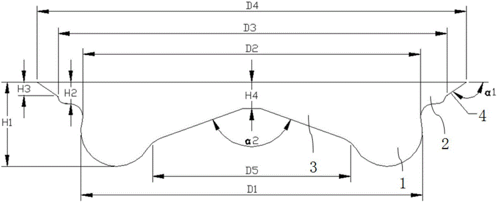
[0017] Such as figure 1 As shown, the chamfered lip combustion chamber of the present embodiment D1=76.4mm, H1=19mm, D2=75mm, H2=4.8mm, D3=87mm, H3=3.05mm, D4=94mm, H4=6mm, H5= 40mm, α1=130-160°, α2=130-150°.
[0018] After fluid dynamic calculation, this design scheme shows that compared with the double-lip combustor of the original machine, under the same NOx emission, the fuel consumption of the A100 working condition is reduced by 1.5%.
Login to View More PUM
| Property | Measurement | Unit |
|---|---|---|
| Circle diameter | aaaaa | aaaaa |
Abstract
The invention discloses a diesel engine beveled lip combustion chamber which comprises a combustion chamber concave pit area, a lip area and a central boss area, wherein the diagonal line of the lip area and the top surface of a piston form a certain angle to eliminate a closed angle; the concave pit area is connected with the lip area and protrudes out of the external part of the combustion chamber; the central boss area is connected with the concave pit area and protrudes towards the internal part of the combustion chamber; and oblique planes on two sides of the central boss area form a certain angle to reduce invalid volume and increase compression ratio. According to the diesel engine beveled lip combustion chamber, through beveling the lip area, the crack risk of a piston is reduced, and reliability of the piston is improved.
Description
technical field [0001] The patent of the present invention relates to a combustion chamber with obliquely cut lips for a diesel engine. Background technique [0002] Energy saving and emission reduction has become an urgent problem to be solved in the field of internal combustion engines. It is not possible to simultaneously reduce fuel consumption and NOx emissions in a diesel engine. This is because the diesel engine is a diffusion combustion, and the fuel injected into the cylinder is concentrated in the local combustion, resulting in local high temperature and oxygen deficiency, generating a large amount of soot, affecting fuel consumption, and generating NOx in the oxygen-enriched area. In order to reduce emissions, the most ideal combustion mode should weaken the early mixing, accelerate the middle and late combustion, reduce emissions and improve combustion efficiency by controlling the combustion heat release rate. [0003] In order to further reduce fuel consumpti...
Claims
Login to View More Application Information
Patent Timeline
 IPC IPC(8): F02B23/00
CPCF02B23/00Y02T10/12
Inventor 陈长军胡芳包宁金华玉赵伟王宏李鹏陈海娥崔晓娟侯福建
Owner CHINA FIRST AUTOMOBILE