Automatic electromagnetic valve adjusting circuit and method thereof

An automatic adjustment and solenoid valve technology, which is applied to valve details, valve devices, engine components, etc., can solve problems such as program control circuit on-off sensitivity, system failure, and damage to the internal structure of the solenoid valve, so as to prevent excessive reverse current The effect of burning the coil

Active Publication Date: 2017-04-26
SINO EURO MATERIALS TECH OF XIAN CO LTD
View PDF5 Cites 1 Cited by
  • Summary
  • Abstract
  • Description
  • Claims
  • Application Information

AI Technical Summary

Problems solved by technology

[0002] In recent decades, with the continuous complexity of working conditions, the traditional solenoid valve control has been gradually replaced by the start solenoid valve. Pneumatic solenoid valves require uninterrupted air supply, and the compressed air will contain moisture, which affects the internal structure of the solenoid valve. there will be damage
However, due to the complexity of the traditional solenoid valve control circuit, and the voltage required by the main circuit and the control circuit are very different, the main circuit coil generally requires AC 220V, and the control circuit and sensor circuit generally require DC 24V, and the circuit is controlled by the program. On-off is

Method used


Image

  • Automatic electromagnetic valve adjusting circuit and method thereof

Examples


Embodiment Construction

[0024] The present invention will be described in further detail below in conjunction with the accompanying drawings and specific embodiments.

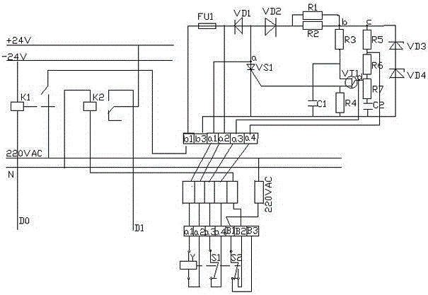
[0025] The present invention is applied to powder sieving machine equipment. The powder sieving machine is based on the use of screen mesh to achieve the purpose of separating part of the powder. The separation is carried out under the protection environment of inert gas (argon, helium) to prevent the powder from being oxidation. The equipment uses the switch of the solenoid valve to control the pressure of the cabin (inert gas content). If the gas content is too high, the safety valve will automatically open to waste gas. If the gas content is too low, oxygen will flow in and the powder will be oxidized. Therefore, the pressure of the gas inside the system is adjusted by continuously switching the electromagnetic valve, so as to maintain the inert gas of the equipment within a constant value range.

[0026] see figure 1 , the solen...


PUM


Abstract

The invention relates to an automatic electromagnetic valve adjusting circuit and a method thereof. The automatic electromagnetic valve adjusting circuit comprises a coil K1 connected with a fuse FU1. The fuse FU1 is connected with a coil Y and a thyristor VS1. After a rectifier diode VD2 is connected with a resistor R1 and a resistor R2, the rectifier diode VD2 is connected with a resistor R3, a resistor R4 and a voltage stabilizing diode VD3. An audion VT1 is connected with the resistor R3 and connected with a capacitor C1 in parallel. A control loop of an electromagnetic valve is connected with a base electrode of the audion VT1 through a resistor R5 via a contact S1 and connected with a potentiometer R7. The potentiometer R7 is connected with the resistor R5, a resistor R6 and a capacitor C2 in series. One path of the audion VT1 is connected with the resistor R4, and the other path of the audion VT1 is connected with a trigger circuit of the thyristor VS1. A contact S2 is connected with 220VAC current and an electromagnetic valve Y. A coil K2 is connected with a controller B2 and a power source null line, and the coil K2 is connected with a +24V power source. The control loop of the circuit is completely separated from the power source and control of the electromagnetic valve, the situation that in the electromagnetic valve operation process, interference is caused to the controller due to overcurrent or reverse signals is avoided, and damage of the electromagnetic valve due to the sudden power getting or power losing is prevented.

Description

technical field [0001] The invention belongs to the technical field of circuit design, and in particular relates to an electromagnetic valve automatic adjustment circuit and a method thereof. Background technique [0002] In recent decades, with the increasingly complex working conditions, the traditional solenoid valve control has been gradually replaced by the start solenoid valve. Pneumatic solenoid valves require uninterrupted air supply, and the compressed air will contain moisture, which affects the internal structure of the solenoid valve. There will also be damage. However, due to the complexity of the traditional solenoid valve control circuit, and the voltage required by the main circuit and the control circuit are very different, the main circuit coil generally requires AC 220V, and the control circuit and sensor circuit generally require DC 24V, and the circuit is controlled by the program. On and off are too sensitive. [0003] Especially in the detection of a...

Claims


Application Information

Patent Timeline
IPC IPC(8): F16K31/06
CPCF16K31/0679
Inventor 吴昊陈小林张鹏杜康王晓荣王庆相梁书锦张平祥
Owner SINO EURO MATERIALS TECH OF XIAN CO LTD
Why Eureka
Try Eureka