
Dust-proof device used for air conditioner

A dust-proof device and air-conditioning technology, applied in air-conditioning systems, applications, household heating, etc., can solve problems such as loss, energy waste, and greenhouse effect, and achieve the effects of beautiful structure, reduced production materials, and reduced labor force

Inactive Publication Date: 2017-04-26
新昌县黑磁铁室内设计有限公司
View PDF1 Cites 0 Cited by
  • Summary
  • Abstract
  • Description
  • Claims
  • Application Information

AI Technical Summary

Problems solved by technology

[0002] At present, the split air conditioners sold in the market, according to the customer's specific appearance requirements, have both a symmetrical appearance structure on the left and right sides of the tuyere, and an asymmetrical appearance structure on the left and right sides of the tuyere. These appearances reflect the different aesthetic needs and use requirements of users. At present, while the air conditioning system is cooling, it will emit heat equivalent to the cooling capacity into the atmosphere according to the principle of energy conservation. This will not only cause waste heat pollution in the atmosphere, but also produce a greenhouse effect. At the same time, people have to consume additional electricity. It seems that there is no loss of heat energy on the surface, but in fact it is accompanied by the loss of entropy during the conversion of heat energy form, which is undoubtedly a waste of energy. Therefore, the consumption should be as much as possible Less energy provides a comfortable environment for buildings, focusing on the dual benefits of energy saving and environmental protection, which has become the research and development direction of the current air conditioning system. The application number is a pressure type air conditioning structure described in CN201320824575.6, although it is in the evaporation unit A sealed cavity is set in the outer casing to adjust the air temperature in the cabin and at the same time the sealed cavity structure isolates the external air and ensures the gas safety in the cabin, but it does not have the functions of dustproof and lighting

Method used


Image

  • Dust-proof device used for air conditioner
  • Dust-proof device used for air conditioner

Examples


Embodiment Construction

[0013] In order to make the technical means, creative features, goals and effects achieved by the present invention easy to understand, the present invention will be further described below in conjunction with specific embodiments.

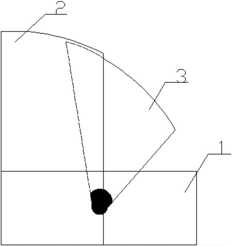
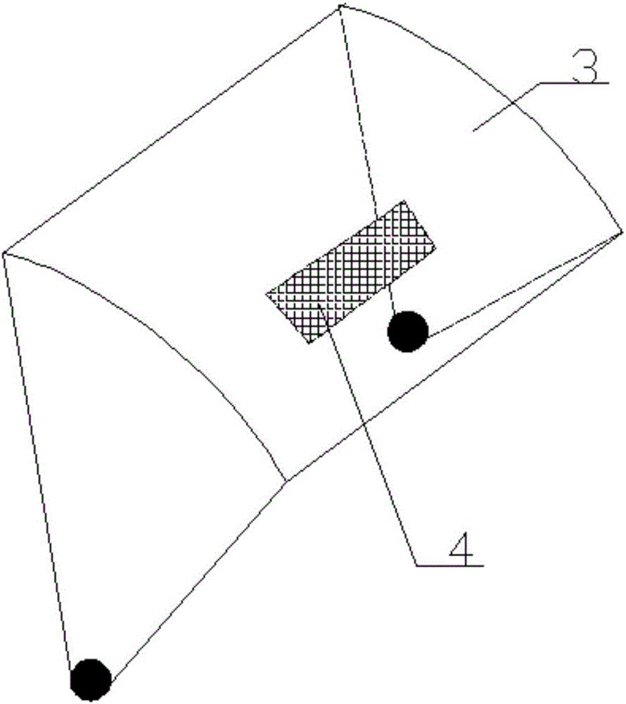
[0014] Such as figure 1 and figure 2 As shown, a dust-proof device for air-conditioning includes an air-conditioning body 1, a first dust-proof shelf 2 and a second dust-proof shelf 3, and the first dust-proof shelf 2 is arranged above the air-conditioning body 1 and is connected to the air-conditioning body 1. The air conditioner body 1 is fixedly connected together, and the second dustproof frame 3 is arranged below the first dustproof frame 2 and is rotatably connected with the air conditioner body 1 .

[0015] It is worth noting that the first dust-proof frame 2 and the second dust-proof frame 3 are both arc-shaped structures, which facilitate the rotation of the second dust-proof frame 3 and reduce the production materials. The structure is...


PUM


Abstract

The invention discloses a dust-proof device used for an air conditioner, and relates to the field of household daily necessities. The dust-proof device comprises an air conditioner body, a first dust-proof rack and a second dust-proof rack. The first dust-proof rack is arranged above the air conditioner body and fixedly connected with the air conditioner body. The second dust-proof rack is arranged below the first dust-proof rack and rotatably connected with the air conditioner body. According to the dust-proof device used for the air conditioner, the first dust-proof rack is fixedly connected above the air conditioner body and is capable of blocking dust above the air conditioner; and the second dust-proof rack is rotatably connected to the air conditioner body, rotates upwards when the air conditioner works, and rotates downwards when the air conditioner is not in use, so that the dust-proof device has an integral dust-proof function for the air conditioner body.

Description

technical field [0001] The invention relates to the field of household daily necessities, in particular to a dustproof device for an air conditioner. Background technique [0002] At present, the split air conditioners sold in the market, according to the customer's specific appearance requirements, have both a symmetrical appearance structure on the left and right sides of the tuyere, and an asymmetrical appearance structure on the left and right sides of the tuyere. These appearances reflect the different aesthetic needs and use requirements of users. At present, while the air conditioning system is cooling, it will emit heat equivalent to the cooling capacity into the atmosphere according to the principle of energy conservation. This will not only cause waste heat pollution in the atmosphere, but also produce a greenhouse effect. At the same time, people have to consume additional electricity. It seems that there is no loss of heat energy on the surface, but in fact it is...

Claims


Application Information

Patent Timeline
IPC IPC(8): F24F13/20
CPCF24F13/20F24F2221/02
Inventor 杨帅君
Owner 新昌县黑磁铁室内设计有限公司
Learn More