Method and system for detecting image quality of optical system, and testing target plate
A technology of optical system and test target, applied in the field of optics, can solve problems such as inability to accurately measure products, and achieve fast speed, high efficiency, and good repetition rate
- Summary
- Abstract
- Description
- Claims
- Application Information
AI Technical Summary
Problems solved by technology
Method used
Image
Examples
Embodiment 1
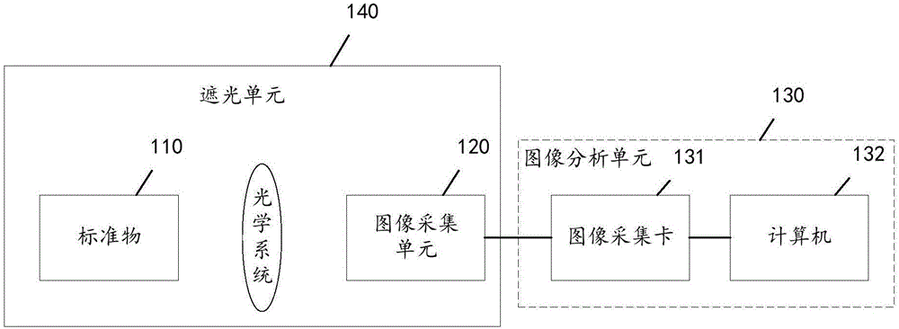
[0025] figure 1 It is a schematic structural diagram of a system for detecting the image quality of an optical system provided by an embodiment of the present invention, as shown in figure 1 As shown, the system for detecting the image quality of an optical system provided in this embodiment includes: a standard object 110 , an image acquisition unit 120 , and an image analysis unit 130 .
[0026] The standard object 110 is placed at the focal length of the object side of the optical system. The standard object 110 can include a test target plate and a surface light source. The test target plate is located between the surface light source and the optical system to be tested. Under the illumination of the surface light source, the test target plate Display graphics for measuring various optical parameters of the optical system; the standard object 110 can also be a display screen with a driving circuit, and the driving circuit drives the display screen to display graphics for m...
Embodiment 2
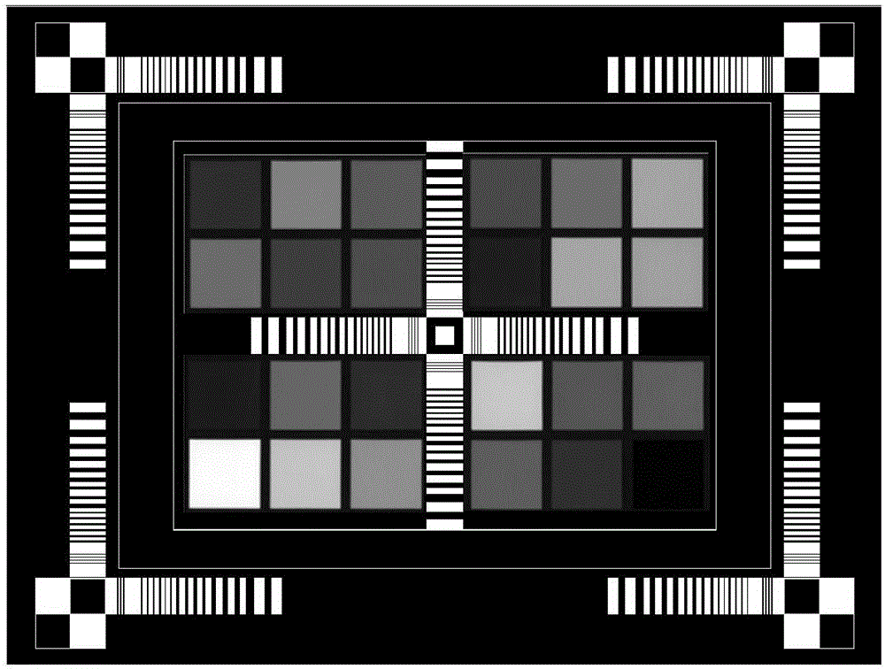
[0033] figure 2 is a schematic diagram of a test target provided by an embodiment of the present invention, such as figure 2 As shown, the test target plate provided in this embodiment can display a graph of various optical parameters for testing the optical system under the illumination of a light source, and the graph includes multiple image features for measuring different optical parameters.
[0034] The figure displayed on the test target board is a rectangle with pure black as the background color, and is symmetrical with the horizontal centerline and vertical centerline of the rectangle.
[0035]The center and four corners of the rectangle are respectively provided with checkerboard areas for measuring the contrast of the optical system. In a specific embodiment, a white square is set in the center of the checkerboard area in the center of the rectangle, and 2*2 black and white squares are set in the checkerboard area at the four corners of the rectangle. The relati...
Embodiment 3
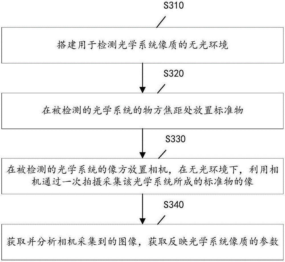
[0042] image 3 It is a flowchart of a method for detecting the image quality of an optical system provided by an embodiment of the present invention, such as image 3 As shown, the method for detecting the image quality of an optical system provided in this embodiment includes:
[0043] Step S310: Build a dark environment for detecting the image quality of the optical system to prevent external light from affecting the detection results.
[0044] Step S320: placing a standard object at the focal length of the object side of the optical system to be inspected, so that the light containing object information passes through the optical system to be inspected and becomes parallel light.
[0045] The standard object can be a display screen with a driving circuit, and the driving circuit drives the display screen to display graphics for measuring various optical parameters of the optical system; or, the standard object includes a test target plate and a surface light source, and t...
PUM
 Abstract
Description
Claims
Application Information
 - R&D
- Intellectual Property
- Life Sciences
- Materials
- Tech Scout
- Unparalleled Data Quality
- Higher Quality Content
- 60% Fewer Hallucinations
Browse by: Latest US Patents, China's latest patents, Technical Efficacy Thesaurus, Application Domain, Technology Topic, Popular Technical Reports.
© 2025 PatSnap. All rights reserved.Legal|Privacy policy|Modern Slavery Act Transparency Statement|Sitemap|About US| Contact US: help@patsnap.com


