Wheel disc type multi-filter IR-CUT switch

An IR-CUT and optical filter technology, applied in optics, instruments, optical components, etc., can solve problems such as uncontrollable precision, low control precision, and small carrying capacity, and achieve high automation, excellent imaging quality, and manufacturing low cost effect

Inactive Publication Date: 2017-04-26
东莞市维斗科技股份有限公司
View PDF6 Cites 9 Cited by
  • Summary
  • Abstract
  • Description
  • Claims
  • Application Information

AI Technical Summary

Problems solved by technology

However, the switchers in the prior art generally have the following disadvantages: 1) Low control precision: only two fixed positions, open and close, have no precision during movement, and the position precision of open and close is also relatively low (compared with plastic molding and assembly operations). , switching times, fixture accuracy, etc.), the accuracy cannot be controlled, and the driving error is large; 2) The driving force is poor: it can only drive single-chip or double-chip and small-sized filters, the carrying capacity is small, and due to the use of electromagnetic The driving of the valve is limited by the force arm & swing angle and the force of the movement space; 3) Poor impact resistance and anti-interference ability: rely on static holding force to stay in a fixed position, and the static force is relatively small, so it can only be used in stationary applications such as bolts. or vibration-free lens and environment
4) Poor stability: due to the use of solenoid valves for driving and no guide post guidance, the driving stability and consistency are poor

Method used


Image

  • Wheel disc type multi-filter IR-CUT switch
  • Wheel disc type multi-filter IR-CUT switch
  • Wheel disc type multi-filter IR-CUT switch

Examples


Embodiment 1

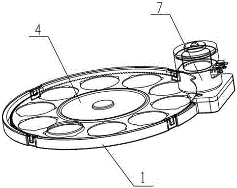
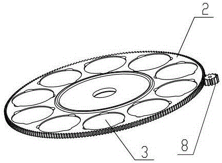
[0027] In this example, if figure 2 As shown, the roulette 2 is provided with one, the center of the fixed seat 1 is provided with a fixed shaft, the roulette is rotatably connected to the fixed shaft, the outer periphery of the roulette 2 is provided with teeth, and the power of the driving device 7 The output end is provided with a driving gear 8 , and the driving gear 8 is meshed with the wheel disc 2 . When the controller controls the driving device 7 to operate, the driving device 7 drives the driving gear 8 to rotate, and the driving gear 8 drives the wheel 2 to rotate, so that the optical filter 3 on the wheel 2 approaches or moves away from the light through hole.

Embodiment 2

[0029] In this example, if Figure 5 As shown, there are two roulettes 2, the center of the fixed seat 1 is provided with a fixed shaft, and the roulettes 2 are respectively rotatably connected with the fixed shafts, and the outer circumference of each roulette 2 is provided with teeth, and the The power output end of the driving device 7 is provided with a driving gear 8 , and the driving gear 8 meshes with the two wheels 2 at the same time. When the controller controls the driving device 7 to act, the driving device 7 drives the driving gear 8 to rotate, and the driving gear 8 simultaneously drives the two wheel discs 2 to rotate in the same direction, so that the optical filter on the wheel disc 2 is close to or away from the light through hole .

[0030] In this embodiment, by setting the colors of the upper and lower filters, the effect of each filter is preset, and different light transmissions are achieved through gear rotation.

Embodiment 3

[0032] In this example, if Figure 6 As shown, there are two roulettes 2, the center of the fixed seat 1 is provided with a fixed shaft, and the roulettes 2 are respectively rotatably connected with the fixed shafts, and the outer circumference of each roulette 2 is provided with teeth, and the The power output end of the driving device 7 is provided with a driving gear 8 , and the driving gear 8 meshes with the wheel disc 2 through a reduction gear set 9 . When the controller controls the driving device 7 to act, the driving device 7 drives the driving gear 8 to rotate, and the driving gear 8 drives the two wheel discs 2 to rotate in reverse through the reduction gear set 9 at the same time, so that the optical filter 3 on the wheel disc 2 is close to or away from the clear hole.

[0033] Further, such as Figure 7As shown, the reduction gear set 9 includes first to third combination gears, and the second combination gear and the third combination gear are located on both s...


PUM


Abstract

The invention discloses a wheel disc type multi-filter IR-CUT switch, which relates to the technical field of supporting devices each provided with an objective lens, an additional lens, an optical filter cover or a rotary table and the like. The switch comprises a container-shaped fixing base, wherein one or more wheel discs are arranged in the fixing base, a plurality of via holes are formed in the periphery of each wheel disc, a filter is arranged in each via hole, the filters on the same wheel disc are of different types, a cover plate covers on the fixing base, so that an accommodating cavity for the wheel discs is formed by means of the fixing base and the cover plate, an upper light-transmitting hole is formed in the cover plate, a lower light-transmitting holes is formed in the fixing base, the upper light-transmitting hole and the light-transmitting hole are positioned in a facing manner, and the upper light-transmitting hole and the light-transmitting hole are positioned in a manner of facing one filter; and a driving device is arranged outside the accommodating cavity, and the driving device is connected with the wheel disc by means of a transmission device. The wheel disc can load a large number of filters of different types and of the same thickness or different thickness, the optical filtering effect is good, and the imaging quality is excellent.

Description

technical field [0001] The invention relates to the technical field of a support device with an objective lens, an additional lens, a filter cover or a rotating table, and in particular to a wheel-type multi-filter IR-CUT switcher. Background technique [0002] The IR-CUT switcher refers to a set of filters built in the camera lens group. When the infrared sensing point outside the lens detects the change in the intensity of light, the built-in IR-CUT automatically switches the filter according to the external The intensity of the light is automatically switched accordingly, so that the image can achieve the best effect. However, the switchers in the prior art generally have the following disadvantages: 1) Low control precision: only two fixed positions, open and close, have no precision during movement, and the position precision of open and close is also relatively low (compared with plastic molding and assembly operations). , switching times, fixture accuracy, etc.), the...

Claims


Application Information

Patent Timeline
Patent Type & Authority Applications(China)
IPC IPC(8): G03B17/14G02B7/00
CPCG02B7/006G03B17/14
Inventor 钟木生杨俊文赵少伟
Owner 东莞市维斗科技股份有限公司
Why Eureka
Try Eureka