
A carrier rocket information integrated electrical system

A launch vehicle and electrical system technology, applied to electrical components, transmission systems, electrical testing/monitoring, etc., can solve problems such as large state changes on the rocket, no autonomous control function, and complicated testing process, so as to reduce the demand for testers , strong flexibility and adaptability, and the effect of simplifying the composition of system equipment

Active Publication Date: 2020-02-28
SHANGHAI AEROSPACE SYST ENG INST
View PDF6 Cites 0 Cited by
  • Summary
  • Abstract
  • Description
  • Claims
  • Application Information

AI Technical Summary

Problems solved by technology

[0003] The traditional electrical system of the launch vehicle is still dominated by point-to-point analog cable communication. Except for the rocket-borne computer, other control devices on the rocket have no independent control function, the level of intelligence is low, and the composition of the rocket-borne equipment and the system information flow are complicated. There are mainly the following disadvantages:
[0004] 1) The degree of intelligence is not enough
[0005] The calculation functions of the stand-alone computer on the arrow are all concentrated in the computer on the arrow, and other control equipment has no independent control function, the workload of the calculation on the arrow is heavy, and the intelligence of the control equipment on the arrow is low
[0006] 2) Low level of automation
[0007] Due to the use of point-to-point analog cable communication, the test process is mostly based on ground excitation-arrow action-ground sampling. The test process is complicated, and there are many arrow-ground interfaces. Low, insufficient level of automation
[0008] 3) Integration and generalization are not high
[0009] Due to the need to configure a large number of excitation and sampling equipment for ground testing, the ground testing equipment is huge, the system information flow is complex, and the level of integration is low; the specificity of the arrow and ground equipment is strong, and it is difficult to achieve universal design. Poor adaptability

Method used


Image

  • A carrier rocket information integrated electrical system

Examples


Embodiment Construction

[0040] Hereinafter, the integrated electrical system of the launch vehicle information of the present invention will be described in further detail with reference to the accompanying drawings and specific embodiments. According to the following description and claims, the advantages and features of the present invention will be clearer. It should be noted that the drawings all adopt a very simplified form and all use imprecise ratios, which are only used for the purpose of conveniently and clearly assisting in describing the embodiments of the present invention.

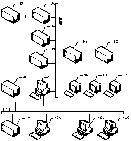
[0041] figure 1 As shown, a carrier rocket information integrated electrical system provided by the present invention includes: on-arrow centralized control equipment, ground centralized control equipment, on-arrow measurement and monitoring equipment, and ground measurement and monitoring equipment, wherein the on-arrow centralized control equipment, The ground centralized control equipment and the on-board measuremen...


PUM


Abstract

The invention relates to a carrier rocket information integration electrical system consisting of an on-rocket centralized control device, a ground centralized control device, an on-rocket measurement and monitoring device and a ground measurement and monitoring device The on-rocket centralized control device automatically performs the centralized control of a carrier rocket in the carrier rocket flight process; the ground centralized control device controls the on-rocket work state during the ground testing; the on-rocket measurement and monitoring device monitors the running parameters of the systems of the rocket; the ground measurement and monitoring device is used to monitor the running parameters that characterize the working condition of the carrier rocket during the ground test; and the rocket and ground data communication of the whole electrical system is carried out via a 1553B bus, and the ground carries out the data communication via Ethernet. The carrier rocket electrical system is characterized by integration, versatility, integration and automation.

Description

Technical field [0001] The invention relates to the field of launch vehicle electrical systems, in particular to a launch vehicle information integrated electrical system. Background technique [0002] The launch vehicle is the foundation of space activities, and the electrical system is an important part of the launch vehicle. By constantly sensing the real-time flight status of the launch vehicle, controlling the rocket to fly according to the predetermined orbit, adjusting the rocket attitude in real time, and obtaining real-time status parameters of the rocket through sensors to characterize Operating status of the launch vehicle. [0003] The traditional electrical system of the launch vehicle still relies mainly on point-to-point analog cable communication. Except for the computer on the rocket, no other control equipment on the rocket has autonomous control functions. The level of intelligence is low, and the composition of the equipment on the rocket and the system informat...

Claims


Application Information

Patent Timeline
Patent Type & Authority Patents(China)
IPC IPC(8): G05D1/10G05B23/02H04L29/08
Inventor 辛高波周恒保丁秀峰高莉秦英明王猛
Owner SHANGHAI AEROSPACE SYST ENG INST
Learn More