
Synchronous rectification control circuit, power converter and control method thereof

A technology of power converter and synchronous rectification, which is applied in the direction of converting DC power input to DC power output, converting device of output power, adjusting electrical variables, etc., and can solve problems such as damage and abnormal operation of power converters.

Active Publication Date: 2017-04-26
HANGZHOU SILAN MICROELECTRONICS
View PDF6 Cites 5 Cited by
  • Summary
  • Abstract
  • Description
  • Claims
  • Application Information

AI Technical Summary

Problems solved by technology

The turn-off delay of the synchronous switching tube leads to the simultaneous conduction of the main switching tube and the synchronous switching tube, resulting in a large shoot-through current, which makes the power converter work abnormally and even damages the power converter.
[0005] Therefore, the existing synchronous rectification control method has limitations when applied to the current continuous mode

Method used


Image

  • Synchronous rectification control circuit, power converter and control method thereof
  • Synchronous rectification control circuit, power converter and control method thereof
  • Synchronous rectification control circuit, power converter and control method thereof

Examples


Embodiment Construction

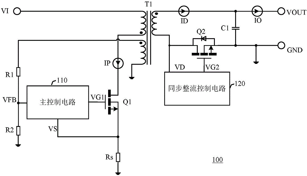
[0054] Hereinafter, the present invention will be described in more detail with reference to the accompanying drawings. In the various figures, identical elements are indicated with similar reference numerals. For the sake of clarity, various parts in the drawings have not been drawn to scale. Also, some well-known parts may not be shown.

[0055] In the following, many specific details of the present invention are described, such as device structures, materials, dimensions, processing techniques and techniques, for a clearer understanding of the present invention. However, the invention may be practiced without these specific details, as will be understood by those skilled in the art.

[0056] In this application, the term "coupled" means a direct connection or an indirect connection between two modules or elements. In the case of an indirect connection, one or more intermediate modules or elements may be included between two modules or elements. The term "power terminal" m...


PUM


Abstract

The present invention discloses a synchronous rectification control circuit, a power converter and a control method thereof. The synchronous rectification control circuit comprises a continuous current time detection circuit which is coupled to the power end of a synchronous switch tube and is used for obtaining a continuous current time signal, a rectification time control circuit which is coupled to the continuous current time detection circuit and is used for obtaining continuous current time information according to the continuous current time and thus generating a rectification time control signal, and a logic gate which is used for generating the switch control signal of the synchronous switch tube according to the continuous current time signal and the rectification time control signal, wherein the rectification time control circuit stores the first continuous current time information of a former switch period and compares the first continuous current time information of the former switch period and the second continuous current time information of a current switch period, and thus generates the rectification time control signal so as to avoid the simultaneous conduction of a main switch tube and a simultaneous switch tube. The synchronous rectification control circuit is compatible with a current continuous mode and a current interruption mode.

Description

technical field [0001] The present invention relates to switching power supply technology, and more specifically, to a synchronous rectification control circuit, a power converter and a control method thereof. Background technique [0002] The power converter is a power supply that uses a switching tube to control the charging and discharging process of the energy storage element to supply power, and controls the on-off time ratio of the switching tube to maintain a stable output voltage and / or output current. In an isolated power converter, a transformer is used to isolate the input terminal from the output terminal, and the primary winding of the transformer is used as an energy storage element. Power converters are easily formed into modular and miniaturized integrated circuits, and have been widely used in various charging power sources for mobile phones, tablet PCs and portable media players, as well as in power supplies for driving light-emitting diodes (LEDs). [000...

Claims


Application Information

Patent Timeline
IPC IPC(8): H02M3/335H02M1/38
CPCH02M1/38H02M3/33592H02M1/385Y02B70/10
Inventor 谢小高陈华捷
Owner HANGZHOU SILAN MICROELECTRONICS
Learn More