Cylindrical heat source thermoelectric generation device

A thermoelectric power generation, cylinder technology, applied in the directions of generators/motors, electrical components, etc., can solve the problems of small contact area, insignificant effect, increase generator monomers, etc., to reduce the process of heat conduction and speed up the cold end Heat dissipation and efficiency improvement

Inactive Publication Date: 2017-04-26
JIANGSU UNIV
View PDF6 Cites 1 Cited by
  • Summary
  • Abstract
  • Description
  • Claims
  • Application Information

AI Technical Summary

Problems solved by technology

[0003] The existing thermoelectric power generation modules are all in the shape of a flat plate. When the flat shape is applied to cylindrical heat sources such as exhaust pipes and shock absorbers, there is a problem that the contact area is small and cannot be directly applied.
In the literature with Chinese patent application number 20120540568.3, an external array type thermoelectric generator unit with a natural cold end is proposed. During use, the number of thermoelectric generator units is determined according to the structural size of the heat source. It is connected into a closed loop like a chain, and then the electrodes of these multiple thermoelectric power generation units are connected in series or in parallel according to the requirements of the monomers, and the contact area between the outer wall of the heat source and the thermoelectric power generation unit is increased by increasing the number of generator units. Has a certain effect, but the effect is not obvious
Whether it is to change the size of the power generation module to adapt to the cylindrical heat source as much as possible, or to change the external shape of the heat source to facilitate the installation of the thermoelectric power generation module, for heat to pass through the outer wall of the heat source, the contact gap between the outer wall and the hot end of the thermoelectric power generation module, and finally to the heat source The conduction process of the end plate has not changed, the heat conduction and collection efficiency is low, and the power generation efficiency of the entire thermoelectric power generation device is not ideal

Method used


Image

  • Cylindrical heat source thermoelectric generation device
  • Cylindrical heat source thermoelectric generation device
  • Cylindrical heat source thermoelectric generation device

Examples


Embodiment Construction

[0016] The present invention will be further described below in conjunction with the accompanying drawings and specific embodiments. It should be understood that the following specific embodiments are only for the present invention but not intended to limit the scope of the present invention. It should be noted that, in order to facilitate the display of the device structure, the size of the illustration is not the same as that of the actual device, nor is it proportional.

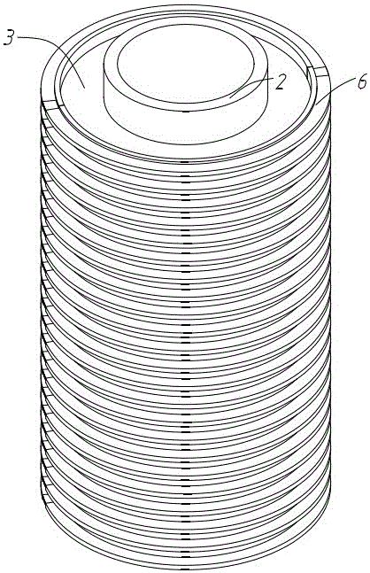
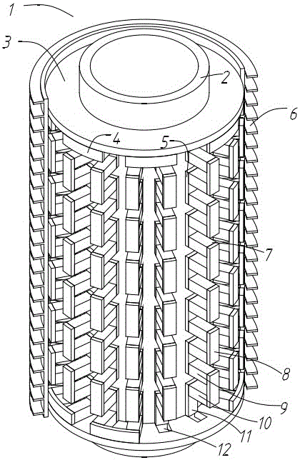
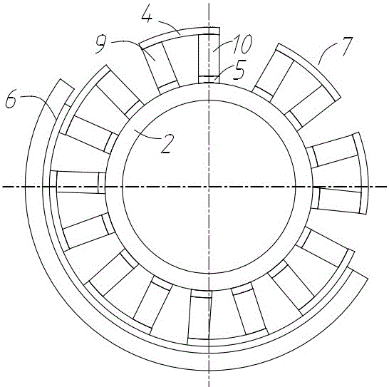
[0017] Such as figure 1 with figure 2 As shown, the cylindrical heat source thermoelectric power generation device 1 of the present invention is installed on the heat source outer wall 2 of a cylinder, including a plurality of P-type semiconductors 9, N-type semiconductors 10, hot-end conductive sheets 5 and cold-end conductive sheets 8, a plurality of P-type semiconductors 9 and N-type semiconductors 10 are connected in series through a plurality of cold-end conductive sheets 8 and hot-end conductive sh...


PUM


Abstract

The invention discloses a cylindrical heat source thermoelectric generation device in the field of energy recovery technology. The device comprises a plurality of P-type semiconductors, a plurality of N-type semiconductors, a plurality of hot-end conductive plates and a plurality of cold-end conductive plates. One P-type semiconductor, one hot-end conductive plate, an N-type semiconductor and a cold-end conductive plate are serially connected in an end-to-end manner, thereby forming a PN junction. All PN junctions are connected in an end-to-end manner, thereby forming a semiconductor chain. The semiconductor chain is arranged in a repeated manner along the axial direction of the external wall of the cylindrical heat source. All hot-end conductive plates are fixedly connected with the external wall of the heat source. All cold-end conductive plates are connected with the inner surface of a heat radiator. The external wall of the heat source is directly used as the heat-end substrate of a thermoelectric generation module. When the heat source operates and radiates heat to outside, because the heat end of the thermoelectric generation module is the outer wall and no superfluous heat conduction process exists, relatively high hot-end temperature and relatively high temperature increase speed are obtained, thereby improving heat conduction efficiency and realizing higher thermoelectric generation efficiency.

Description

technical field [0001] The invention relates to the technical field of energy recovery, in particular to a thermoelectric power generation device, which can recycle and utilize waste heat energy for power generation. Background technique [0002] During the running of a car, a lot of energy is wasted, and the most important form of energy waste is dissipated into the air in the form of heat, including the waste heat of the car engine being discharged through the exhaust pipe, and the vibration energy being converted into heat by the shock absorber. The form is dissipated into the air, etc., and the effective recovery of these waste heat energy can improve the energy utilization efficiency of the car. There are many ways to recover energy. Compared with other energy recovery methods, the thermoelectric power generation energy recovery device has less changes to the original structure of the vehicle components, and does not change the internal structure. At the same time, it ...

Claims


Application Information

Patent Timeline
Patent Type & Authority Applications(China)
IPC IPC(8): H02N11/00
CPCH02N11/002
Inventor 王乐乐何仁樊文渊丁浩
Owner JIANGSU UNIV
Why Eureka
Try Eureka