Electric heater and preparation method thereof

A heater and electric heating element technology, applied in the direction of electric heating devices, ohmic resistance heating, ohmic resistance heating parts, etc., can solve the problems of low heat transfer efficiency of PTC electric heaters, low heat transfer efficiency of electric heaters, and The improvement of thermal efficiency is limited, etc.

Inactive Publication Date: 2017-04-26
谢彦君
View PDF11 Cites 9 Cited by
  • Summary
  • Abstract
  • Description
  • Claims
  • Application Information

AI Technical Summary

Problems solved by technology

[0006] At present, there are many existing technologies that have improved the PTC electric heater, for example: Chinese patent CN201119017Y discloses a PTC electric heater, which makes the longitudinal section of the cooling element into a plurality of triangles arranged side by side. This structure improves the heat transfer efficiency of the PTC electric heater, but the improvement of the heat transfer efficiency is limited, and the side-by-side arrangement also increases the amount of materials
Chinese patent CN201146614Y discloses a PTC electric heater, which is sealed with insulating packing at the end of the PTC core tube (metal flat tube). Although this pa

Method used


Image

  • Electric heater and preparation method thereof
  • Electric heater and preparation method thereof
  • Electric heater and preparation method thereof

Examples


Embodiment 1

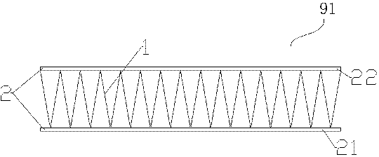
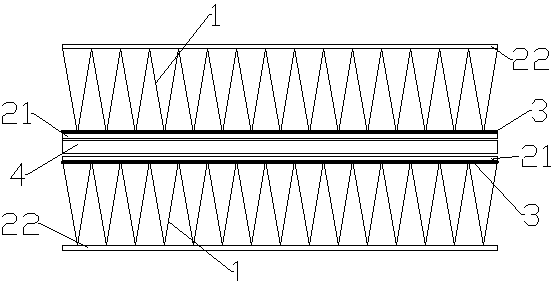
[0109] Such as figure 1 As shown, it is a schematic diagram of an aluminum heat sink 9 (or heat dissipation fin, or heat dissipation element, or aluminum heat dissipation strip, or aluminum strip) provided by the present invention. The heat sink 9 in this embodiment is a heat sink 91 composed of a group of fins 1 and side plates 2 located on both sides of the fins 1 . Such as figure 2 As shown, the heat sink 91 is provided with an insulating layer 3 on the surface attached to the PTC heating element 6 (that is, outside the bottom plate 21 ). That is, an insulating layer 3 is provided between the heat sink 91 and the PTC electric heating element 6 , so that the surface of the heat sink 91 that is not in contact with the PTC electric heating element 6 is not charged.

[0110] Such as image 3 As shown, it is a schematic diagram of a PTC heating element 6 (or PTC electrode strip assembly) provided by the present invention. The upper and lower sides of the PTC element 4 are re...

Embodiment 2

[0119] refer to Figure 8 , is a schematic structural diagram of the heat sink in Embodiment 2 of the present invention. As shown in the figure, the heat sink 9 of this embodiment is another kind of heat sink 92, and the heat sink 92 is composed of the fin 1 and the side plate 2 (ie, the top plate 22) on one side, that is, the heat sink 92 does not include Bottom plate 21. Such as Figure 9 As shown, the side plate 2 on the other side (i.e. the bottom plate 21) is used as the electrode sheet 5, and an insulating layer 3 is provided on the outside of the electrode sheet 5, and then the Figure 8 The heat sink 92 shown is bonded to the outside of the electrode sheet 5 .

[0120] The electric heater of this embodiment can be realized in the following way: two groups such as Figure 9 The components shown are bonded to both sides of several PTC elements 4 to form the electric heater of the present invention. An insulating layer 3 is provided between the heat sink 92 and the P...

Embodiment 3

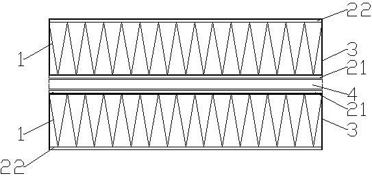
[0127] refer to Figure 11 , is a schematic diagram of the structure of the heat sink and the external insulating layer in the third embodiment of the present invention, which is as in figure 1 The shown heat sink 91 is provided with an insulating layer 3 except for the surface attached to the PTC element 4 . As shown in the figure, the heat sink includes fins 1 and side plates 2 arranged on both sides; Both the outer side and both sides are insulated so as to obtain the insulating layer 3 as shown in the figure. That is, an insulating layer 3 is provided on the heat sink 91 at a portion not in contact with the PTC element 4 , so that the surface of the heat sink 91 not in contact with the PTC element 4 is electrically insulated or not charged. In this embodiment, the bottom plate 21 serves as an electrode sheet at the same time.

[0128] In this embodiment, the setting method of the insulating layer 3 can be: two cooling fins 91 are arranged on both sides of some PTC eleme...


PUM

PropertyMeasurementUnit
Thermal conductivityaaaaaaaaaa
Insulation resistanceaaaaaaaaaa

Abstract

The invention provides an electric heater and a preparation method thereof. The electric heater comprises at least one PTC electric heating element and a heat radiation piece. The PTC electric heating element comprises positive and negative electrode pieces and a PTC element between the positive and negative electrode pieces. The heat radiation piece is at the outer surface of PTC electric heating element. In the heat radiation piece, a surface which is not in contact with the PTC electric heating element is not charged, an aluminum flat tube or aluminum tube in the prior art is not used by the electric heater, the cost is saved, the thermal resistance of an aluminum flat tube intermediate link is reduced, the efficiency of heat transfer is improved, and the volume power density is increased.

Description

[0001] The patent application for the present invention is a divisional application. The application number of the original application is CN201580032481.7, the application date is July 21, 2015, and the title of the invention is: an electric heater and its preparation method. technical field [0002] The invention relates to an electric heater (or electric heater) and a preparation method thereof, in particular to a PTC electric heater with higher heat exchange efficiency without using metal flat tubes and a preparation method thereof. Background technique [0003] PTC is the English abbreviation of "Positive Temperature Coefficient". PTC material has the characteristics of heat-sensitive, current-limiting, and time-delay switching, and has the characteristics of no contact, no noise, and long service life. Therefore, as a new type of thermistor material, its main application can be divided into two types: switching and heating big category. For example, in the field of s...

Claims


Application Information

Patent Timeline
IPC IPC(8): H05B3/10H05B3/02
CPCH05B3/10H05B3/02H05B2203/02
Inventor 不公告发明人
Owner 谢彦君
Why Eureka
Try Eureka