

Control method of air fryer
An air fryer and control method technology, applied in the field of kitchen appliances, can solve problems such as device and component life and stability threats, and achieve the effects of improving cooking efficiency, preventing thermal shock, and accelerating temperature reduction
- Summary
- Abstract
- Description
- Claims
- Application Information
AI Technical Summary
Problems solved by technology
Method used
Image

Examples
Embodiment 1
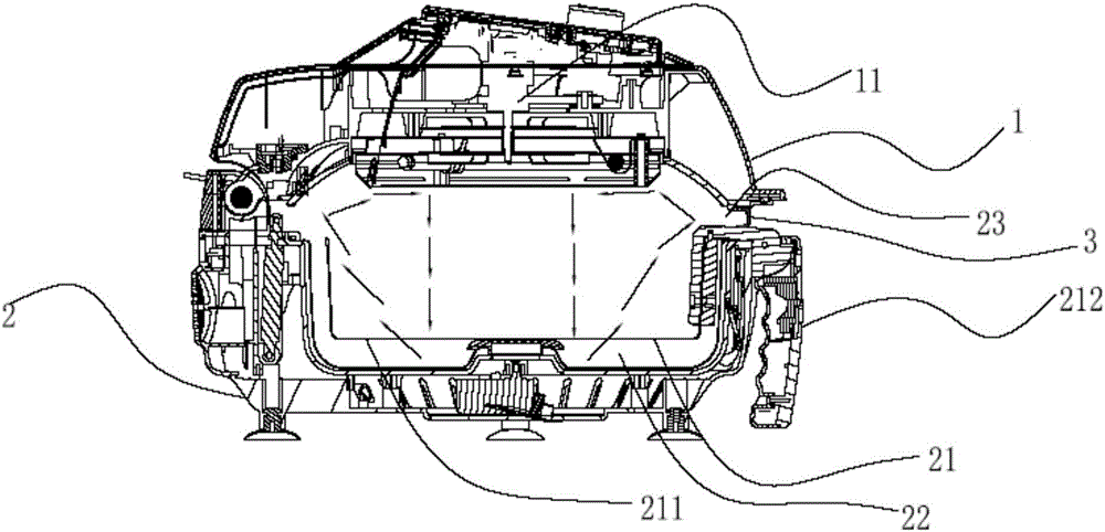
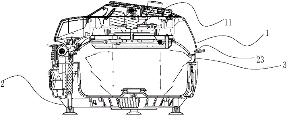
[0041] Such as Figure 1-4 As shown, an air fryer includes an upper shell 1 and a lower shell 2, the lower shell 2 is provided with a cavity 3, and a fryer 7 can be detachably set in the cavity 3, and the fryer 7 cooperates with the cavity 3 to form a cooking chamber 31, and the upper housing 1 is provided with a hot air device, a control unit, an air duct 6, and a thermal fuse 8, and the control unit and the hot air device are arranged above the cooking chamber 3. The hot air device comprises a heating element 41, a fan 42 and a motor 43, the heating element 41 comprises a plane spiral electric heating tube, the fan 42 is arranged above the plane spiral electric heating tube, and the fan 42 comprises an upper blade 44 and a lower blade 45, A cover plate 46 is provided between the upper blade 44 and the lower blade 45, and the cover plate 46 and the upper casing 1 form an accommodating cavity 11, and a control unit is arranged in the accommodating cavity 11, and the control unit...
Embodiment 2
[0056] The difference between the second embodiment and the first embodiment lies in that the setting of the air outlet and the rotational speed of the motor are different.
[0057] The size of the air outlet 9 is adjustable. In this embodiment, the air outlet 9 is provided with movable blades, similar to the form of shutters. When in the cooking stage, the blades are vertically arranged, so that the air outlet is relatively small, effectively ensuring heat Circulate in the cooking cavity 31 to heat the food; when in the transition stage, the blades are set horizontally, so that the air outlet is larger, and more airflow can flow out through the air outlet, which accelerates the cooling process and reduces the impact of the hot air flow .
[0058] In this embodiment, in the transition stage, the main control board controls the motor to work at maximum power through the thyristor, thereby driving the fan to move at high speed, accelerating the air flow, and realizing rapid cool...
Embodiment 3
[0062] The difference between the third embodiment and the first embodiment is that the time for the fan to continue working is judged by the temperature sensor.
[0063] Such as Figure 5-6 As shown, in this embodiment, the fan has a built-in motor, and the main control board can directly control the speed of the fan through electrical signals, and there is no need to set a separate motor to drive the fan, and the structure is simpler. And in this embodiment, a temperature sensor 10 is provided in the upper casing, and the temperature sensor 10 is arranged close to and above the hot air device. Since the temperature sensor is relatively close to the hot air device, the influence of the rising thermal air flow can be accurately tested.
[0064] In the transition stage, the heating element stops working, and the fan 42 continues to work to drive the air circulation in the cooking cavity and the upper casing; in the end stage, a preset temperature T is set in the main control b...
PUM
 Abstract
Description
Claims
Application Information