Method for preventing fiber breaking at root of hollow fiber ultrafiltration membrane

An ultrafiltration membrane and fiber technology, applied in ultrafiltration, chemical instruments and methods, membrane technology, etc., can solve the problems of easy breakage of membrane filaments, decline in mechanical properties, and decrease in tensile strength of membrane filaments against breakage. The effect of wire breakage

Inactive Publication Date: 2017-05-10
WUHAN AQUCELL MEMBRANE TECH
View PDF7 Cites 5 Cited by
  • Summary
  • Abstract
  • Description
  • Claims
  • Application Information

AI Technical Summary

Problems solved by technology

However, the biggest disadvantage of hollow fiber ultrafiltration membranes compared with flat ultrafiltration membranes and tubular ultrafiltration membranes is that they are easy to break. Even international famous brands still cannot completely eliminate the occurrence of broken filaments.
[0003] The typical structure of the hollow fiber ultrafiltration membrane module is a membrane bundle composed of several membrane filaments. One or both ends of the membrane filaments are sealed in the potting glue. The wire becomes brittle, the mechanical properties decrease, and the wire is easily broken under the action of external force
At present, the commonly used protection measure for the root of the membrane filament is to pour soft glue into the junction of the membrane filament and the potting glue. This method can greatly reduce the broken filaments at the root, but the climbing of the soft glue will still make the membrane filament breakage resistant. The tensile ability has decreased, and the broken wire at the root cannot be completely eliminated
[0004] The method described in the Chinese patent "Hollow Fiber Membrane Module with the Function of Preventing Hollow Fiber Ultrafiltration Membrane from Broken Filament" with the application number CN200720072974.6 is to use a single-layer protective sleeve, and the single-layer protective sleeve will wrap the membrane filaments too tightly and the glue will It is difficult to completely penetrate into the gap between the membrane filaments, and the cast components will leak; if the protective sleeve wraps the membrane filaments too loosely, it will not be able to effectively protect the roots of the membrane filaments, and the swing and longitudinal movement of the membrane filaments will still be transmitted to the The root of the membrane filament to make the membrane filament easy to break

Method used


Image

  • Method for preventing fiber breaking at root of hollow fiber ultrafiltration membrane
  • Method for preventing fiber breaking at root of hollow fiber ultrafiltration membrane

Examples


Embodiment 1

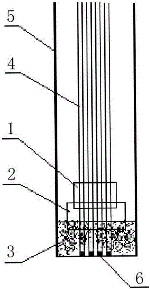
[0020] Cut the bottom of the root of the film tow with a circumference of about 20cm to be cast flat, plug the hole for 1-2mm with a known conventional method, and wrap a piece of self-adhesive coil with a diameter of 25cm*5cm*3.5mm and a Shore hardness of 90 tightly at a distance At 6cm from the end face of the plugging hole of the membrane tow, wrap another piece of self-adhesive coiled material of the same size on the membrane tow so that it is 3cm away from the end of the plugging hole of the membrane tow, overlapping with the aforementioned self-adhesive coil by 2cm, and then wrap the membrane tow Put it into the membrane module cylinder, put it into the suitable mold together, add epoxy resin adhesive to submerge the second layer of protection 2cm, remove the mold after the epoxy resin is cured, and spread the excess sealing material along the module cylinder resection.

Embodiment 2

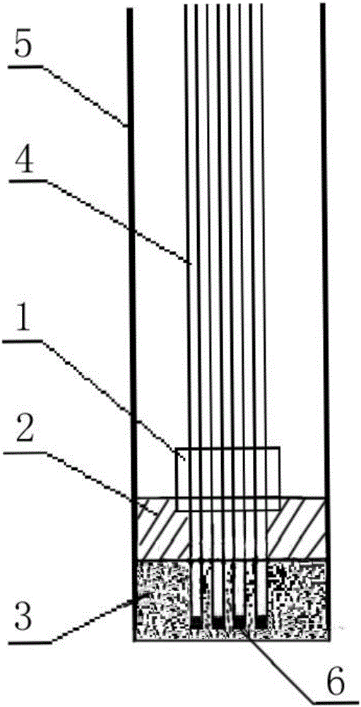
[0022] Cut the bottom of the membrane tow with a circumference of about 20 cm to be cast flat, plug the hole for 1 to 2 mm by a known conventional method, and take a piece made of silica gel, polyethylene, polyvinyl chloride, polyurethane, polystyrene, etc. The viscoelastic plastic is coated with self-adhesive on one side, the size specification is 25cm*10cm*3.5mm, the Shore hardness is 20, the anti-adhesive release paper of the self-adhesive is torn off, and tightly wound on the distance Wrap another piece of viscous elastic plastic of the same size on the membrane tow at 10 cm from the end face of the membrane tow plugging hole so that it is 3 cm away from the end of the membrane tow plugging hole, and overlap with the aforementioned self-adhesive coil by 4 cm, and then wrap the membrane tow Put the membrane component cylinder into the suitable mold together, add epoxy resin adhesive to submerge the second protective layer by 1cm, remove the mold after the epoxy resin is cure...

Embodiment 3

[0024] Cut the membrane tow with a circumference of about 20cm to be cast flat, and plug the hole 1-2mm with a known method, and tightly wind a piece of 25cm*5cm*2mm self-adhesive coiled material at a distance of 6cm from the end of the membrane tow to plug the hole. Put the membrane filaments into the membrane module cylinder, put them into the suitable mold together, add polyurethane adhesive to 2cm beyond the end face of the membrane module cylinder, take off the mold after the epoxy glue is cured, and remove the excess along the membrane module cylinder. Remove the sealing material, and then add soft epoxy resin glue to the membrane module cylinder to submerge the protective layer by 2cm, until the epoxy resin glue is cured.


PUM


Abstract

The invention discloses a method for preventing fiber breaking at the root of a hollow fiber ultrafiltration membrane. The method comprises the following steps: (1) the end surface of a to-be-cast end at the bottom of the root of membrane fiber strand of the hollow fiber ultrafiltration membrane is cut flat, and holes are blocked by 1-2 mm; (2) the to-be-cast end of the membrane fiber strand is wrapped with a sealing layer, a second protective layer and a first protective layer from bottom to top, the second protective layer integrally connects the first protective layer with the sealing layer, the first protective layer is 6-10 cm away from the end surface of the to-be-cast end, and the overlapped part of the second protective layer and the first protective layer is 2-4 cm. With the adoption of the method, the situation that membrane fibers become crisp and break due to glue climbing during glue filling can be prevented.

Description

technical field [0001] The invention relates to the technical field of hollow fiber ultrafiltration membranes, and more particularly, relates to a method for preventing root breakage of hollow fiber ultrafiltration membranes. Background technique [0002] Hollow fiber ultrafiltration membranes have been widely used in sewage treatment, water reuse, separation and concentration, direct drinking water and other fields. However, the biggest disadvantage of hollow fiber ultrafiltration membranes compared with flat ultrafiltration membranes and tubular ultrafiltration membranes is that they are easy to break. Even internationally renowned brands still cannot completely eliminate the occurrence of broken filaments. [0003] The typical structure of the hollow fiber ultrafiltration membrane module is a membrane bundle composed of several membrane filaments. One or both ends of the membrane filaments are sealed in the potting glue. The wire becomes brittle, the mechanical propertie...

Claims


Application Information

Patent Timeline
Patent Type & Authority Applications(China)
IPC IPC(8): B01D63/02B01D61/18
CPCB01D63/02B01D61/145B01D61/18
Inventor 陈泉学
Owner WUHAN AQUCELL MEMBRANE TECH
Why Eureka
Try Eureka