High-precision automatic robot welding device and working method thereof

An automatic welding and robot technology, applied in the field of grid plates, can solve the problems affecting the quality of welding, difficult to complete the process, cumbersome operation, etc., to improve the accuracy of detection, solve the placement problem, and simplify the working process

Active Publication Date: 2017-05-10
苏州鹄珂智能科技有限公司
View PDF10 Cites 5 Cited by
  • Summary
  • Abstract
  • Description
  • Claims
  • Application Information

AI Technical Summary

Problems solved by technology

At present, many enterprises use robots for welding, and the cost is relatively high. Because the welding operation of steel grid plates is too cumbersome, and it is not a special customization of welding products, some processes are difficult or impossible to complete. The existing There will be a lot of metal dust in the production environment of steel grating, and the detectio

Method used


Image

  • High-precision automatic robot welding device and working method thereof
  • High-precision automatic robot welding device and working method thereof
  • High-precision automatic robot welding device and working method thereof

Examples


Embodiment

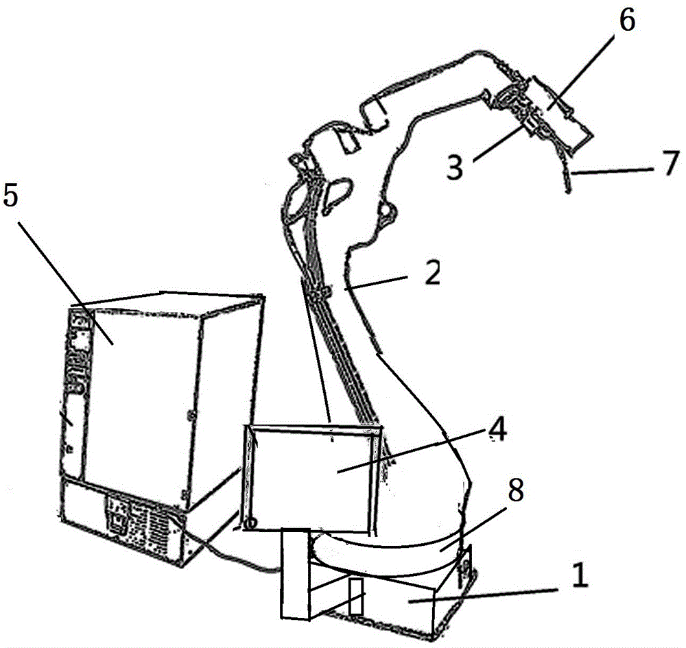
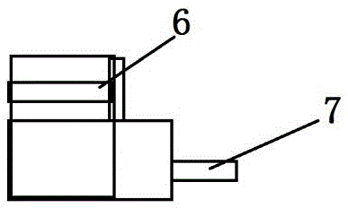
[0042] Such as Figure 1 to Figure 3 A high-precision robotic automatic welding device shown includes: a base 1, a mechanical arm 2, a wrist joint 3, a touch screen 4 and a control device 5, and the wrist joint 3 is provided with a laser detector 6 and a welding torch 7;

[0043] The relationship between the above components is as follows:

[0044] Wherein, the mechanical arm 2 is set on the base 1, the wrist joint 3 is set at the end of the mechanical arm 2, the touch screen 4 is set on the support frame of the base 1, the mechanical arm 2, wrist The joint 3, the touch screen 4 and the laser detector 6 are all connected to the control device 5, the control device 5 is provided with an electric control box, and the detection range of the laser detector 6 is greater than or equal to the required welding edge of the grid plate width.

[0045] In this embodiment, the wrist joint 3 is provided with an installation base, and the installation base is in an inverted L shape. The in...

Embodiment 2

[0054] Such as Figure 1 to Figure 3 A high-precision robotic automatic welding device shown includes: a base 1, a mechanical arm 2, a wrist joint 3, a touch screen 4 and a control device 5, and the wrist joint 3 is provided with a laser detector 6 and a welding torch 7;

[0055] The relationship between the above components is as follows:

[0056] Wherein, the mechanical arm 2 is set on the base 1, the wrist joint 3 is set at the end of the mechanical arm 2, the touch screen 4 is set on the support frame of the base 1, the mechanical arm 2, wrist The joint 3, the touch screen 4 and the laser detector 6 are all connected to the control device 5, the control device 5 is provided with an electric control box, and the detection range of the laser detector 6 is greater than or equal to the required welding edge of the grid plate width.

[0057] In this embodiment, the wrist joint 3 is provided with an installation base, and the installation base is in an inverted L shape. The in...


PUM


Abstract

The invention discloses a high-precision automatic robot welding device for grid plate welding. The high-precision automatic robot welding device comprises a base, a mechanical arm, a wrist joint, a touch screen and a control device, wherein a laser detector and a welding gun are arranged on the wrist joint; the mechanical arm is arranged on the base; the wrist joint is arranged at the end part of the mechanical arm; the touch screen is arranged on a supporting frame of the base; the mechanical arm, the wrist joint, the touch screen and the laser detector are all connected with the control device; an electric control box is arranged in the control device; and the detection range of the laser detector is greater than or equal to the width of a welding edge required by a grid plate. According to the high-precision automatic robot welding device, the mounting base is arranged on the wrist joint; the mounting base is inversely L-shaped; a first mounting hole for mounting the laser detector and a second mounting hole for mounting the welding gun are formed in the mounting base; the first mounting hole is higher than the second mounting hole, so that damage to the laser detector during welding of the welding gun is avoided; and meanwhile, the high-precision automatic robot welding device can effectively guarantee detection of the laser detector in the whole process.

Description

technical field [0001] The invention belongs to the field of grid plates, and in particular relates to a high-precision robot automatic welding device and a working method thereof. Background technique [0002] Steel grating carbon dioxide gas is mainly used for edge sealing of steel grating. Most welding companies still use manual welding for welding. The workload is very heavy. At the same time, due to the large number of people in the welding process Most of them are welded with the naked eye, and the quality of the welding is not stable enough. Due to the poor controllability of people, it is difficult to keep the quality of the welding consistent. Because the welding points are relatively dense, the technical requirements for welding workers are high. The matching of position and parameters is not easy to maintain the best. During the welding process, problems of false welding and missing welding often occur, and the gas generated during the welding process will cause c...

Claims


Application Information

Patent Timeline
IPC IPC(8): B23K37/02B23K37/00B23K31/02
CPCB23K31/02B23K37/00B23K37/02
Inventor 张敏强
Owner 苏州鹄珂智能科技有限公司
Why Eureka
Try Eureka