Rotary polishing device for sheet material

A plate and rotating end technology, applied in grinding drive devices, automatic grinding control devices, grinding machines, etc., can solve the problems of reducing the labor intensity of operators, not realizing fully automatic grinding, and long manual processing time, achieving convenient turning, The effect of strong novelty and low maintenance cost

Active Publication Date: 2017-05-10
安徽基石伟业环保科技有限公司
View PDF7 Cites 6 Cited by
  • Summary
  • Abstract
  • Description
  • Claims
  • Application Information

AI Technical Summary

Problems solved by technology

[0002] At present, grinding and polishing are mainly divided into two methods: manual processing and mechanical processing. The traditional manual processing mainly uses sandpaper or polishing machine for manual grinding and polishing, which has the defects of low efficiency, high labor intensity, long manual processing time and incomplete processing. Mechanical processing has liberated labor force to a certain extent, and prior art such as CN204893641U has announced a kind of plate grinding device, comprises workbench, driving device and clamping device, and the driving device that is set has reduced the labor intensity of operator
However, when double-sided grinding is required, manual flipping is required, and fully automatic grinding has not been realized. Therefore, a plate grinding device that can rotate the plate is needed

Method used


Image

  • Rotary polishing device for sheet material
  • Rotary polishing device for sheet material
  • Rotary polishing device for sheet material

Examples


Embodiment Construction

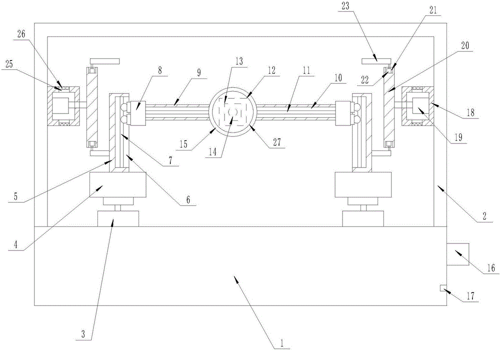
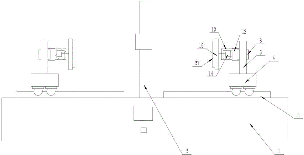
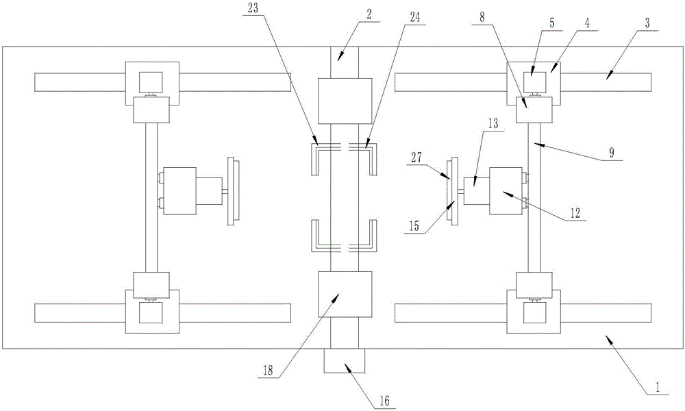
[0015] The present invention is specifically described below in conjunction with accompanying drawing, as Figure 1-3 As shown, a plate rotary grinding device includes a workbench (1), the center of the upper surface of the workbench (1) is provided with a gantry (2), and the upper surface of the workbench (1) is located on the door-shaped A group of No. 1 slide rails (3) is provided on both sides of the frame (2), and No. 1 electric trolleys (4) are all arranged on the described No. 1 slide rails (3), and each of the No. 1 electric trolleys (4 ) upper surface is provided with support rods (5), and a No. 1 slideway (6) is all processed on the surface of each support rod (5) on one side, and each No. 1 slideway (6) is provided with No. two slide rails (7), described each No. two slide rails (7) are all provided with No. two electric trolleys (8), and are connected with horizontal plate ( 9), the surface of each horizontal plate (9) is processed with a No. 2 slideway (10), and ...


PUM


Abstract

The invention discloses a rotary polishing device for a sheet material. The rotary polishing device comprises a worktable, wherein a portal frame is arranged at the center of the upper surface of the worktable; one group of No.1 slide rail is arranged on the upper surface of the worktable and is located at each of two sides of the portal frame; a No.1 electric trolley is arranged on each group of No.1 slide rail; a supporting rod is arranged on the upper surface of each No.1 electric trolley; a No.1 slide way is machined on the surface at one side of each supporting rod; a No.2 slide rail is arranged in each No.1 slide way; a No.2 electric trolley is arranged on each No.2 slide rail; a controller is arranged on the surface at one side of the worktable; an electric supply interface is arranged below the controller; and an input end of the controller is electrically connected with the No.1 electric trolleys, the No.2 electric trolleys, No.3 electric trolleys and No.1 rotary motors respectively. The rotary polishing device for the sheet material has the beneficial effects of simplicity in operation, automation in polishing, convenience for overturning and manpower unleashing; and the physical safety of workers is guaranteed and the working efficiency is improved.

Description

technical field [0001] The invention relates to the field of plate rotary grinding, in particular to a plate rotary grinding device. Background technique [0002] At present, grinding and polishing are mainly divided into two methods: manual processing and mechanical processing. The traditional manual processing mainly uses sandpaper or polishing machine for manual grinding and polishing, which has the defects of low efficiency, high labor intensity, long manual processing time and incomplete processing. Mechanical processing has liberated the labor force to a certain extent, and prior art such as CN204893641U discloses a kind of plate grinding device, comprises workbench, drive device and clamping device, and the drive device provided reduces the labor intensity of operator. However, when double-sided grinding is required, manual flipping is required, and fully automatic grinding has not been realized. Therefore, a plate grinding device that can rotate the plate is needed. ...

Claims


Application Information

Patent Timeline
Patent Type & Authority Applications(China)
IPC IPC(8): B24B19/24B24B41/06B24B41/02B24B47/12B24B51/00
CPCB24B19/24B24B41/02B24B41/06B24B47/12B24B51/00
Inventor 封红雨
Owner 安徽基石伟业环保科技有限公司
Why Eureka
Try Eureka