Controllable mechanism type stacking robot driven by electric push cylinders

A palletizing robot and electric push technology, applied in the field of machinery, can solve the problems of high precision, high speed and high load movement impact, high precision requirements for hydraulic parts manufacturing, hydraulic system is easily affected by environmental factors, etc., to achieve safety Reliable work, compact structure, smooth motion and increased reliability

Inactive Publication Date: 2017-05-10
GUANGXI UNIV
View PDF1 Cites 4 Cited by
  • Summary
  • Abstract
  • Description
  • Claims
  • Application Information

AI Technical Summary

Problems solved by technology

At present, many link-type robots are hydraulic, which has a series of advantages such as simple structure, low manufacturing cost, and large working space. However, their stiffness and strength are generally not high, and they are not suitable for high-precision, high- In the case of high speed and high load, and the motion shock is also large
And for the hydraulic type, not only the manufacturing precision of the hydraulic parts is high, the manufacturing and maintenance costs are high, the hydraulic oil is easy to fail due to heat during work, the cost of replacing the hydraulic oil is high, and the hydraulic system is easily affected by environmental factors, especially In a low temperature or high temperature environment, it is prone to weakness or damage to the hydraulic system

Method used


Image

  • Controllable mechanism type stacking robot driven by electric push cylinders
  • Controllable mechanism type stacking robot driven by electric push cylinders
  • Controllable mechanism type stacking robot driven by electric push cylinders

Examples


Embodiment 1

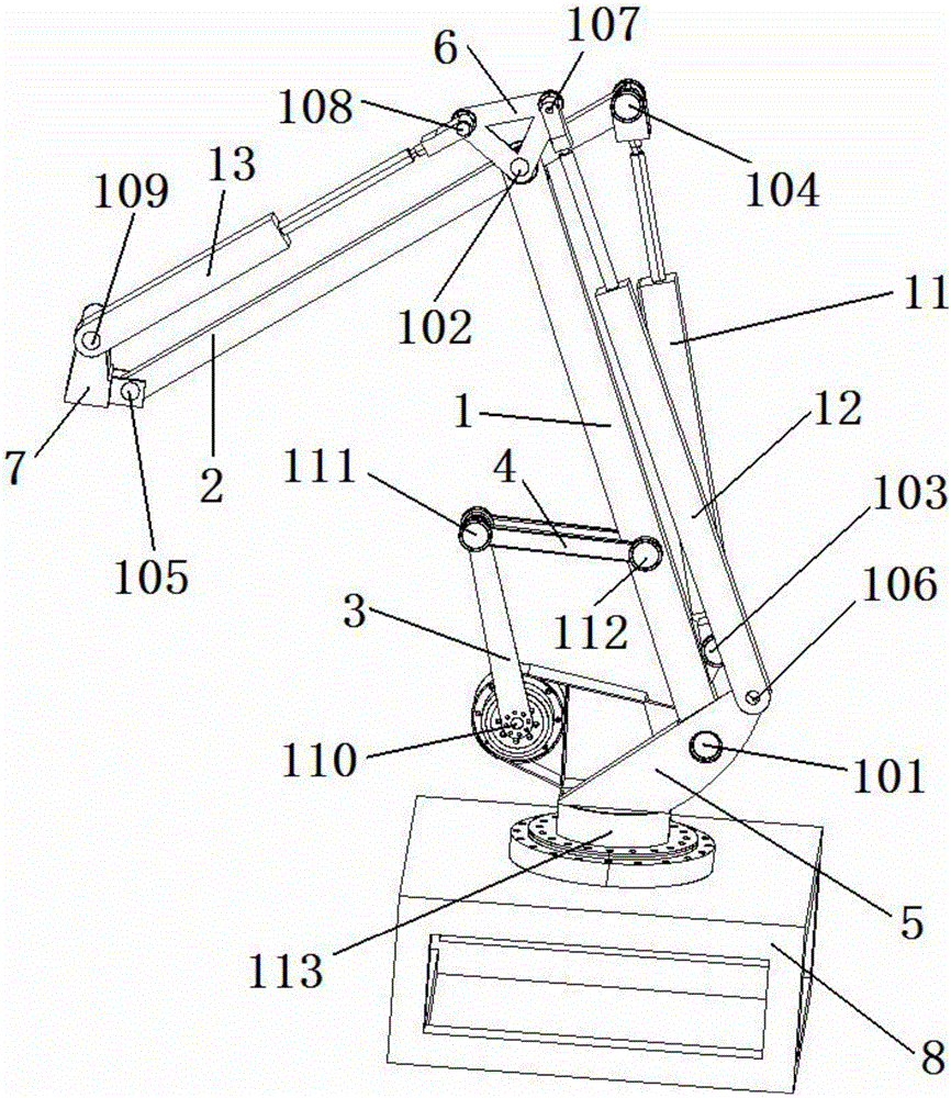
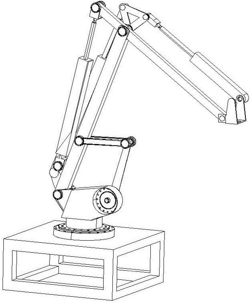
[0014] An electric push cylinder-driven controllable mechanism palletizing robot, including a base 8, a frame 5, a connecting rod 1, a connecting rod 2, a connecting rod 3, a connecting rod 4 4, a triangular connecting plate 6, and an electric push cylinder One 11, electric push cylinder two 12, electric push cylinder three 13 and execution terminal 7,

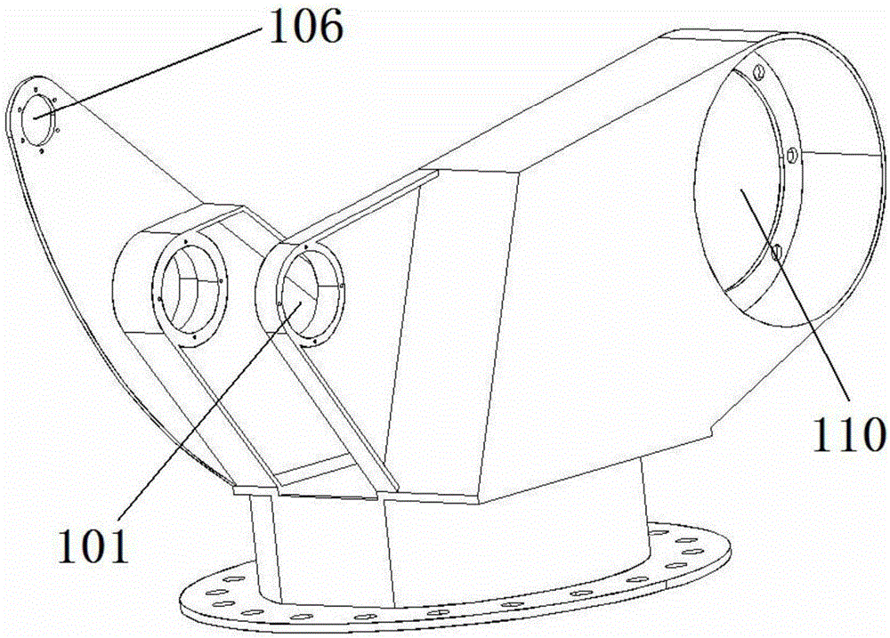
[0015] One end of connecting rod one 1 is connected to frame 5 through rotating pair one 101, and the other end of connecting rod one 1 is connected on connecting rod two 2 through rotating pair two 102.

[0016] One end of electric push cylinder one 11 is connected to connecting rod one 1 through rotating pair three 103, the other end of electric pushing cylinder one 11 is connected to one end of connecting rod two 2 through rotating pair four 104, and the other end of connecting rod two 2 is passed through rotating pair five 105 Connected to the execution terminal 7,

[0017] One end of the electric push cylinder two 12 is ...


PUM


Abstract

A controllable mechanism type stacking robot driven by electric push cylinders is characterized in that one end of a connecting rod I is connected with a frame; the other end of the connecting rod I is connected with a connecting rod II; one end of an electric push cylinder I is connected with the connecting rod I; the other end of the electric push cylinder I is connected with one end of the connecting rod II; the other end of the connecting rod II is connected with an executing terminal; one end of an electric push cylinder II is connected with the frame; the other end of the electric push cylinder II is connected with the first angle of a triangular connecting plate; the second angle of the triangular connecting plate is connected with one end of an electric push cylinder III; the other end of the electric push cylinder III is connected with the executing terminal; one end of a connecting rod III is connected with the frame; the other end of the connecting rod III is connected with one end of a connecting rod IV; the other end of the connecting rod IV is connected with the connecting rod I; and the frame is connected with a base. The stacking robot maintains a series of advantages such as simple structure, low manufacturing cost, large working space and compact structure and is improved in transmission efficiency compared with a traditional mechanism; and meanwhile the stacking robot is reduced in rotational inertia and increased in movement stability and reliability and is free of pollution.

Description

technical field [0001] The invention relates to the field of machinery, in particular to an electric cylinder-driven controllable mechanism palletizing robot. Background technique [0002] The emergence of robots has brought about major changes in human life. Robots have a very large labor intensity, and can complete various tasks efficiently in a short period of time, and can also replace humans to complete some difficult and dangerous tasks. work thus ensuring the personal safety of workers. And it gradually accelerated the process of industrialization and became the backbone of industrial development. Therefore, the robot has received attention and promotion from all over the world. [0003] With the continuous advancement of science and technology, the requirements for modern machinery are continuously improved, and the requirements for precision are also gradually improved. At present, many link-type robots are hydraulic, which has a series of advantages such as simp...

Claims


Application Information

Patent Timeline
Patent Type & Authority Applications(China)
IPC IPC(8): B25J9/00B25J9/12B65G61/00
CPCB25J9/00B25J9/0009B25J9/12B65G61/00
Inventor 蔡敢为叶兵韦为周海唐俊杰史缘缘刘怡欣李洪汉吴承亮任华丽唐剑波
Owner GUANGXI UNIV
Why Eureka
Try Eureka