Control system of converter valve hall inner wall cleaning robot

A technology for cleaning robots and control systems, applied in the field of control systems, can solve problems such as low efficiency, high risk, waste of manpower and material resources, etc.

Pending Publication Date: 2017-05-10
ZHEJIANG UNIV OF TECH
View PDF5 Cites 2 Cited by
  • Summary
  • Abstract
  • Description
  • Claims
  • Application Information

AI Technical Summary

Problems solved by technology

[0003] In order to overcome the defects that the cleaning work of the existing wall surface is done manually and professional lifting machines need to be purchased, the efficiency is low, the risk is

Method used


Image

  • Control system of converter valve hall inner wall cleaning robot
  • Control system of converter valve hall inner wall cleaning robot
  • Control system of converter valve hall inner wall cleaning robot

Examples


Embodiment Construction

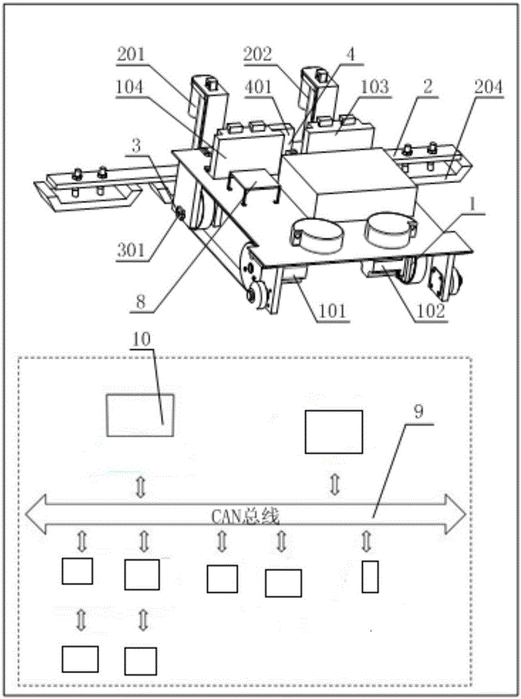
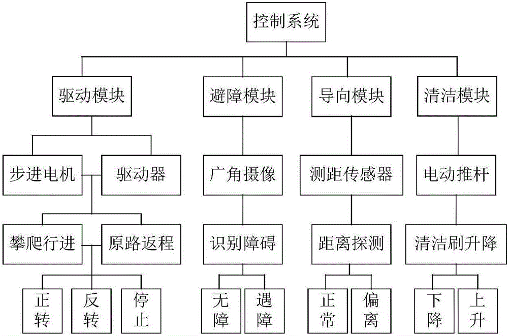
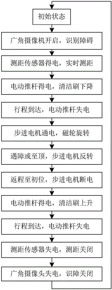
[0023] refer to Figure 1 to Figure 3 , the control system of the cleaning robot for the inner wall of the converter valve hall, including at least one driving module 1, at least one controlled object stepping motor, electric push rods 201, 202, cleaning module 2, guiding module 3, obstacle avoidance module 4, and computer PC Terminal 10, single-chip microcomputer chip 8 and CAN bus 9, described single-chip microcomputer chip 8 is respectively connected with drive module 1, cleaning module 2, guide module 3, obstacle avoidance module 4, computer PC end 10; Wherein,

[0024] Described computer PC end 10 is connected with CAN bus 9, and described computer PC end 10 receives all bus messages from described CAN bus 9, to complete described driving module 1, cleaning module 2, guiding Initialization of module 3 and obstacle avoidance module 4 and monitoring of working status;

[0025] The drive module 1 is connected to the CAN bus 9, and the drive module 1 obtains navigation infor...


PUM


Abstract

The invention discloses a control system of a converter valve hall inner wall cleaning robot. The control system comprises at least one driving module, at least one controlled object stepping motor, an electric push rod, a cleaning module, a guiding module, an obstacle avoidance module, a computer PC terminal, a single chip microcomputer chip and a CAN bus. The computer PC terminal receives all bus information from the CAN bus so as to monitor initialization and the working states of the driving module, the cleaning module, the guiding module and the obstacle avoidance module. The driving module obtains navigation information from the CAN bus and achieves positive rotation, negative rotation and stop of the stepping motor when the robot climbs, advances and goes back the same way through a stepping motor driver. The cleaning module obtains cleaning starting information from the CAN bus, and then ascending and descending of a cleaning brush are achieved by controlling the electric push rod to stretch out and retreat. The descending distance of the cleaning brush is determined by the stroke of the electric push rod. The guiding module controls two distance measurement sensors.

Description

technical field [0001] The invention relates to a control system of a cleaning robot for the inner wall of a converter valve hall. Background technique [0002] The converter station is a station established in the high-voltage direct current transmission system to complete the conversion of direct current and alternating current, and to achieve the safety, stability and power quality of the power system. The converter valve is the core equipment of the DC transmission project. By sequentially connecting the three-phase AC voltage to the DC terminal to obtain the desired DC voltage and realize power control, its value accounts for about 22-25% of the total price of the complete set of equipment in the converter station. . The converter valve hall is a closed building where the converter valve is placed. If the dust accumulated on the inner wall is not cleaned in time, it will spread into the air, which will have a great impact on the normal operation and service life of the...

Claims


Application Information

Patent Timeline
IPC IPC(8): B25J13/08B25J11/00B25J9/16
CPCB25J9/1602B25J11/0085B25J13/08B25J13/089
Inventor 曾晰潘烨计时鸣张书豹苏林杰
Owner ZHEJIANG UNIV OF TECH
Why Eureka
Try Eureka