
Mechanical arm

A technology of manipulators and transmission mechanisms, applied in the field of manipulators, can solve problems such as rough feeding mechanisms, and achieve the effects of saving time, improving production efficiency, and liberating manpower

Inactive Publication Date: 2017-05-10
HOHAI UNIV CHANGZHOU
View PDF10 Cites 9 Cited by
  • Summary
  • Abstract
  • Description
  • Claims
  • Application Information

AI Technical Summary

Problems solved by technology

[0004] At this stage, the unloading mechanism of the loading and unloading devices of most machine tools is relatively rough, or the loading mechanism also has the function of unloading

Method used


Image

  • Mechanical arm
  • Mechanical arm
  • Mechanical arm

Examples


Embodiment Construction

[0025] The present invention will be specifically introduced below in conjunction with the accompanying drawings and specific embodiments.

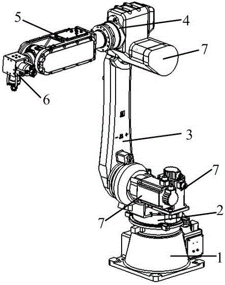
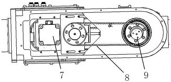
[0026] A manipulator includes a base 1 fixed on a workbench, a swivel waist 2, a large arm 3, a small arm 4, a wrist arm 5 and an actuator 6; the base 1 plays a role of fixing the whole manipulator.

[0027] The swivel waist 2 is set on the base 1, and the motor 7 in the base 1 drives the swivel waist 2 to rotate coaxially on the base 1 through the planetary gear reducer; the planetary gear reducer includes an outer ring 14 and an inner ring 13 on the same axis , and several planetary gears 15 arranged between the outer ring 14 and the inner ring 13 . Powered by the motor 7, the rotation speed and angle of the slewing waist 2 are adjusted through the planetary gear reducer, and the deceleration function is completed through the coordination of the number of teeth between the 9 gears.

[0028] The two ends of the boom 3 are pivotally conn...


PUM


Abstract

The invention discloses a mechanical arm, which comprises a base, a rotary waist, a big arm, a small arm, a cantilever and an executive component. The rotary waist is arranged on the base; a motor in the base drives the rotary waist to rotate on the base through a transmission mechanism; two ends of the big arm are axially connected with the side end of the rotary waist and the small arm; a motor on the end part of the big arm drives the big arm to rotate by adopting a connecting shaft of the rotary waist as an axis through a transmission gear; a motor on the end part of the small arm drives the small arm to rotate by adopting a connecting shaft of the big arm as an axis through a transmission gear; two ends of the cantilever are axially connected with the front end of the small arm and the executive component; a motor built in the cantilever rotates the cantilever through a rotary shaft connected with the small arm; and a belt wheel transmission mechanism connected with the motor rotates the executive component. The mechanical arm provided by the invention is applicable for loading and unloading digital controlled lathe processing pipe type workpieces, and can be used for loading and unloading workpieces with different diameters, so that the manpower is greatly saved, the time is saved, and the production efficiency is improved.

Description

technical field [0001] The invention relates to a manipulator and belongs to the technical field of machinery. Background technique [0002] At present, in the field of mechanical processing, the processing of workpieces often requires multiple processes, and the handling and loading and unloading of workpieces between different processes requires manual operation. Especially on the combined machine tool of the machining center, the efficiency of manual loading and unloading of workpieces is low, and the operation has certain limitations. The error rate, the accuracy of positioning and installation is not enough, and the overall cost is high. [0003] The machine tool loading and unloading device is an integral part of automatic machine tools. It is used for semi-automatic machine tools with high efficiency, short maneuvering time and frequent workpiece loading and unloading. It can significantly improve productivity and reduce physical labor. [0004] At this stage, the un...

Claims


Application Information

Patent Timeline
Patent Type & Authority Applications(China)
IPC IPC(8): B25J18/04B25J15/08B23Q7/04B23B15/00
CPCB25J18/04B23Q7/04B25J15/08
Inventor 苑明海王海东鲁义刚俞红焱王松黄锦婷
Owner HOHAI UNIV CHANGZHOU
Learn More