
Quick-disassembling energy absorption undercarriage for multi-rotor unmanned aerial vehicle
A multi-rotor unmanned aerial vehicle and landing gear technology, applied in the field of aeronautical engineering, can solve the problems of poor buffering effect, small structural deformation, short buffering time, etc., to reduce impact force and impact energy, absorb large energy, and compress large amount of effect
- Summary
- Abstract
- Description
- Claims
- Application Information
AI Technical Summary
Problems solved by technology
Method used
Image

Examples
Embodiment 1
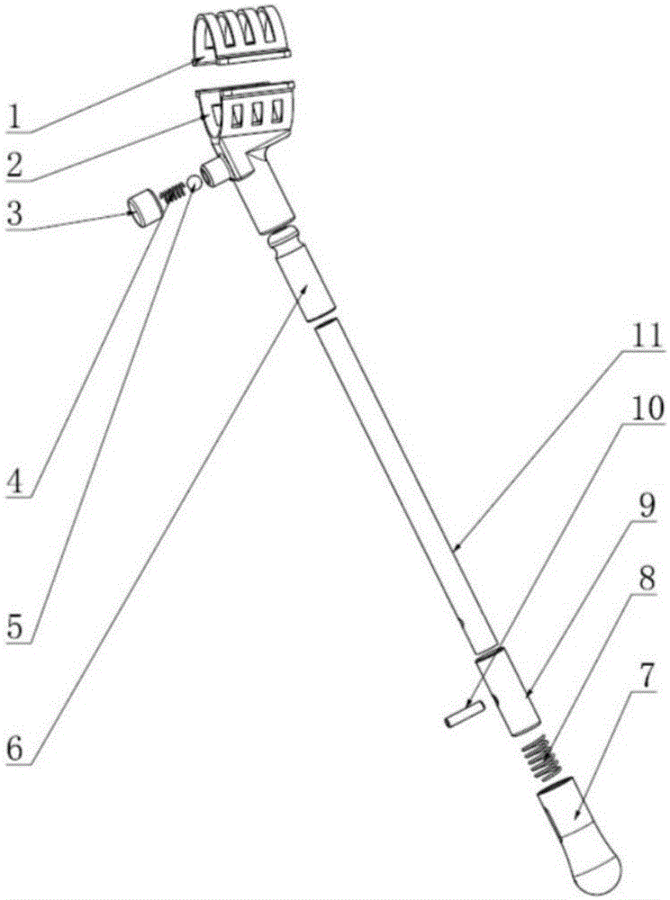
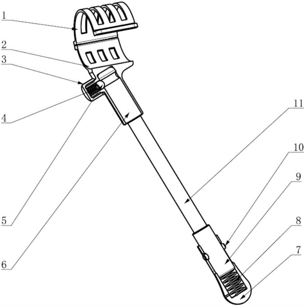
[0038] The invention provides a landing gear for multi-rotor unmanned aerial vehicles which can be quickly assembled and disassembled and spring-buffered. Such as figure 1 As shown, the structure of the landing gear is divided into landing gear struts, fixed structures, quick-release structures and energy-absorbing structures according to their functions. The fixed structure consists of an upper fixed block and a lower fixed block. The upper fixed block is placed directly above the arm of the multi-rotor UAV, and the lower fixed block is placed directly below the arm. The upper fixed block and the lower fixed block are connected by screws. Be fastened between the upper fixed block and the lower fixed block. This fixing method is fixed by the static friction between the upper and lower fixing blocks and the machine arm, without drilling holes on the body of the multi-rotor UAV, and maintaining the overall mechanical properties of the body.
[0039] The quick-release structure...
PUM
 Abstract
Description
Claims
Application Information