
Medical sealing machine provided with bidirectional operation handle

A two-way operation, sealing machine technology, used in packaging sealing/fastening, external support, transportation packaging, etc., can solve problems such as sealing failure, damage to sealing paper, affecting sealing effect, etc., to prevent uneven sealing and prevent overburning Effect

Active Publication Date: 2017-05-10
宁波乔登电子科技有限公司
View PDF9 Cites 3 Cited by
  • Summary
  • Abstract
  • Description
  • Claims
  • Application Information

AI Technical Summary

Problems solved by technology

When using, put the medical device into the sealing paper, and then seal it with a medical sealing machine. The sealing machine on the market compresses and loosens it by pushing and pulling the handle, but in the traditional structure, the handle is pushed to compress and pulled to loosen. The operation is single, which cannot meet the habits of users, and it is very easy to cause uneven sealing during sealing, which leads to sealing failure. Therefore, the position needs to be adjusted during use. When encountering products with wide sealing, there will be poor sealing on both sides. Phenomenon, which in turn affects the sealing effect
In addition, overheating and damage to the sealing paper due to the overtime of the sealing time also frequently occur

Method used


Image

  • Medical sealing machine provided with bidirectional operation handle
  • Medical sealing machine provided with bidirectional operation handle
  • Medical sealing machine provided with bidirectional operation handle

Examples


Embodiment Construction

[0031] The present invention will be further described below in conjunction with the accompanying drawings and specific embodiments.

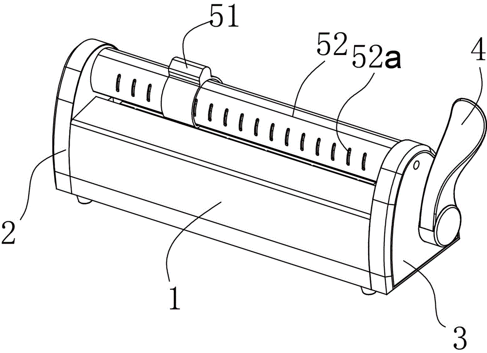
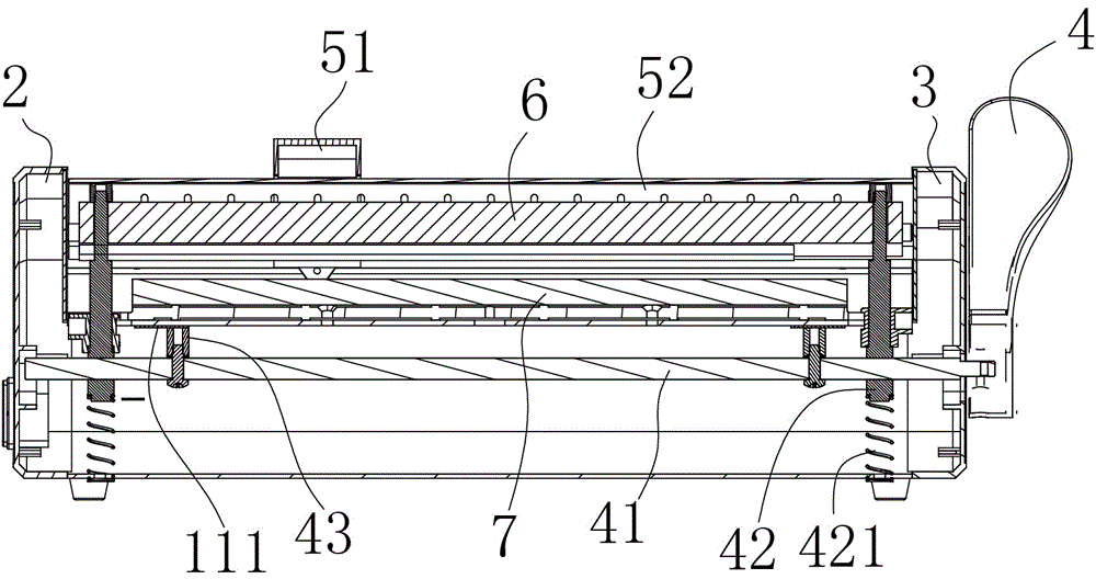
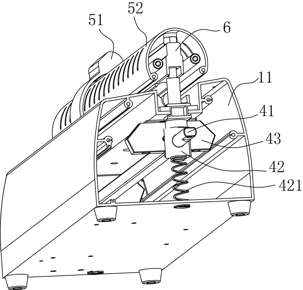
[0032] Attached Figure 1 to Attached Figure 15 The reference signs in are: 1 sealing machine main body, 11 casing, 11a heating groove, 11b first card groove, 11d screw seat, 111 baffle plate, 2 left guard plate, 2a left guide groove, 3 right guard plate, 3a Right guide slot, 4 handle, 41 driving rod, 41a cylinder part, 41b square column part, 42 follower rod, 421 spring, 423 rod head, 423a shaft hole, 424 shaft, 425 fastening nut, 43 skid plate, 43a Skid surface, 43b fourth card slot, 43c screw hole, 43d stress relief groove, 43e stress relief hole, 43f fastening screw, 43g rubber pad, 43k lever assembly, 51 slider, 51a first guide hole, 51b, second Guide hole, 51c third guide hole, 51d ironing surface, 511 blade, 52 guide rail, 52a heat dissipation grid, 52b inner rail, 52c reinforcement rail, 52d heat dissipation cavity, 6 layering strips, ...


PUM


Abstract

The invention discloses a medical sealing machine provided with a bidirectional operation handle. The medical sealing machine is characterized in that the upper ends of driven rods of the machine are connected to a press bar, shaft holes are horizontally formed in the lower ends of the driven rods, a drive rod is rotationally arranged in the shaft holes in a sleeving manner, and bilaterally symmetrical crow plates are fixed radially on the drive rod and below a heating groove; a left protective plate and a right protective plate are screwed and fixed at two ends of a sealing machine main body respectively, a left guide groove and a right guide groove which are corresponding in position are formed in the left protective plate and the right protective plate respectively, two ends of the drive rod are arranged in the left guide groove and the right guide groove respectively, the longitudinal length of each of the left guide groove and the right guide groove is larger than the stroke length between the press bar and a heating assembly, the handle is mounted at one end of the drive rod and on the outer side of the right protective plate, springs are coaxially fixed at the lower ends of the driven rods, and the lower ends of the springs are fixed on a housing; and a guide rail is arranged in parallel above the press bar and glidingly provided with a slide tool. When the machine is used, all that is required is to pull the handle forwards or backwards to the limit so as to press the press bar to the heating assembly, the press bar can be separated from the heating assembly rapidly after the handle is released, and overburning and sealing failure are prevented.

Description

technical field [0001] The invention relates to the field of medical equipment, in particular to a medical sealing machine with a bidirectional operating handle. Background technique [0002] The medical sealing machine is mainly used for sealing medical devices after sterilization in hospital disinfection supply rooms, operating rooms and other departments. It can be used for continuous sealing and parameter printing of paper-plastic bags and sealing paper. When using, put the medical device into the sealing paper, and then seal it with a medical sealing machine. The sealing machine on the market compresses and loosens it by pushing and pulling the handle, but in the traditional structure, the handle is pushed to compress and pulled to loosen. The operation is single, which cannot meet the habits of users, and it is very easy to cause uneven sealing during sealing, which leads to sealing failure. Therefore, the position needs to be adjusted during use. When encountering pro...

Claims


Application Information

Patent Timeline
IPC IPC(8): B65B51/14
CPCB65B51/146B65B51/148
Inventor 黄星王程
Owner 宁波乔登电子科技有限公司
Features
  • Generate Ideas
  • Intellectual Property
  • Life Sciences
  • Materials
  • Tech Scout
  • Unparalleled Data Quality
  • Higher Quality Content
  • 60% Fewer Hallucinations
Learn More