
On-track maintenance supporting device for gear and rack lifting equipment

A technology of lifting equipment and rack and pinion, applied in the field of lifting equipment maintenance device, can solve problems such as failure, failure of driving gear, etc.

Active Publication Date: 2017-05-10
TIANJIN JINHANG COMP TECH RES INST
View PDF4 Cites 10 Cited by
  • Summary
  • Abstract
  • Description
  • Claims
  • Application Information

AI Technical Summary

Problems solved by technology

[0002] Once the driving gear fails in the rack and pinion lifting equipment, the existing braking method that brakes the shaft of the transmission system to stop the driving gear from rotating may not be able to brake reliably. There is a certain distance from the floor position, and the existing method of manually operating the lifting equipment car to the leveling position through the turning device is also invalid due to the failure of the drive gear; therefore, a device that can support on-rail maintenance is required to ensure Safety

Method used


Image

  • On-track maintenance supporting device for gear and rack lifting equipment
  • On-track maintenance supporting device for gear and rack lifting equipment
  • On-track maintenance supporting device for gear and rack lifting equipment

Examples


Embodiment 1

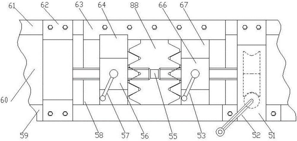
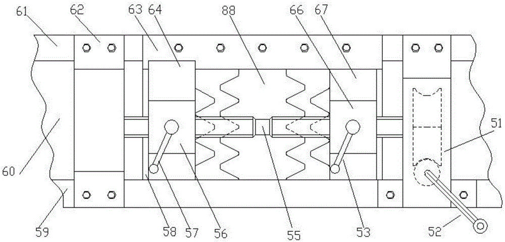
[0040] Example 1, Figure 17 It is a schematic diagram of Embodiment 1, which shows that the on-rail maintenance support device of the rack and pinion lifting equipment is installed on the rack and pinion lifting equipment, the maintenance workbench is put away, the brake is released, and the state is ready to start running, or the appearance of the running state schematic diagram; Figure 12 , Figure 13 , Figure 14 It is also a schematic diagram of embodiment 1, Figure 13 Shows how the maintenance workbench is stowed in the braking state, Figure 14 Indicates that the maintenance workbench is unfolded into the first working state in the braking state, Figure 12 It shows that the maintenance workbench is expanded into the second working state when it is in the braking state; the on-rail maintenance support device for the rack and pinion lifting equipment is equipped with a horizontal electromagnetic independent safety braking device at both ends, and a A retractable m...

Embodiment 2

[0041] Embodiment 2, a rack and pinion elevator installed with the on-rail maintenance support device for the rack and pinion lifting equipment of the present invention, the description of the components and functions of the internal structure of the horizontal electromagnetic pulling independent safety brake device is described in Figure 5-11 As shown, and [0006] paragraph, [0007] paragraph, [0008] paragraph, [0009 paragraph described; the description of the composition and function of each part of the internal structure of the retractable maintenance workbench can be found in Figure 12-20 Shown, and paragraphs [0010], [0011], [0012], [0013], [0014], [0015], and [0016]; the appearance diagrams in different working states are the same as Figure 12 , Figure 13 , Figure 14 , Figure 21 ; The principle of operation is the same as described in paragraph [0034].


PUM


Abstract

The invention discloses an on-track maintenance supporting device for gear and rack lifting equipment. The on-track maintenance supporting device is characterized by comprising at least one independent safety braking device and at least one maintenance worktable; the at least one independent safety braking device independently realizes reliable braking fixation for the lifting equipment without dependence on a driving system of the lifting equipment and comprises a horizontal electromagnetic drive independent safety braking device; when the at least one maintenance worktable is unfolded to be in a first working state, a worker can stand in a lifting equipment car for checking or maintaining equipment closer to the outer part of the lifting equipment car through a window; when the at least one maintenance worktable is unfolded to be in a second working state, the worker can stand on a working platform for checking or maintaining equipment further from the outer part of the lifting equipment car; and the on-track maintenance supporting device realizes the beneficial effects that the effective space is saved, the working efficiency and the working quality are improved, and the safety protection degree is improved.

Description

technical field [0001] The invention relates to the field of lifting equipment maintenance devices, in particular to an on-rail maintenance support device for rack and pinion lifting equipment. Background technique [0002] Once the driving gear fails in the rack and pinion lifting equipment, the existing braking method that brakes the shaft of the transmission system to stop the driving gear from rotating may not be able to brake reliably. There is a certain distance from the floor position, and the existing method of manually operating the lifting equipment car to the leveling position through the turning device is also invalid due to the failure of the drive gear; therefore, a device that can support on-rail maintenance is required to ensure Safety. Contents of the invention [0003] The purpose of the present invention is to provide a method that can support various situations, support the maintenance of the moving parts of the rack and pinion lifting equipment, such ...

Claims


Application Information

Patent Timeline
Patent Type & Authority Applications(China)
IPC IPC(8): B66B5/00B66B9/02
CPCB66B5/0068B66B5/0087B66B9/022
Inventor 廖忠民
Owner TIANJIN JINHANG COMP TECH RES INST
Learn More