Sleeve kiln lime cooling device
A cooling device and sleeve kiln technology, which is applied in the field of sleeve kiln lime cooling devices, can solve the problems of uneven cooling of lime products, uneven distribution of cooling air, burnt product transfer belts, etc., so as to avoid wind segregation and be easy to implement , the effect of simple structure
- Summary
- Abstract
- Description
- Claims
- Application Information
AI Technical Summary
Problems solved by technology
Method used
Image

Examples
Embodiment 1
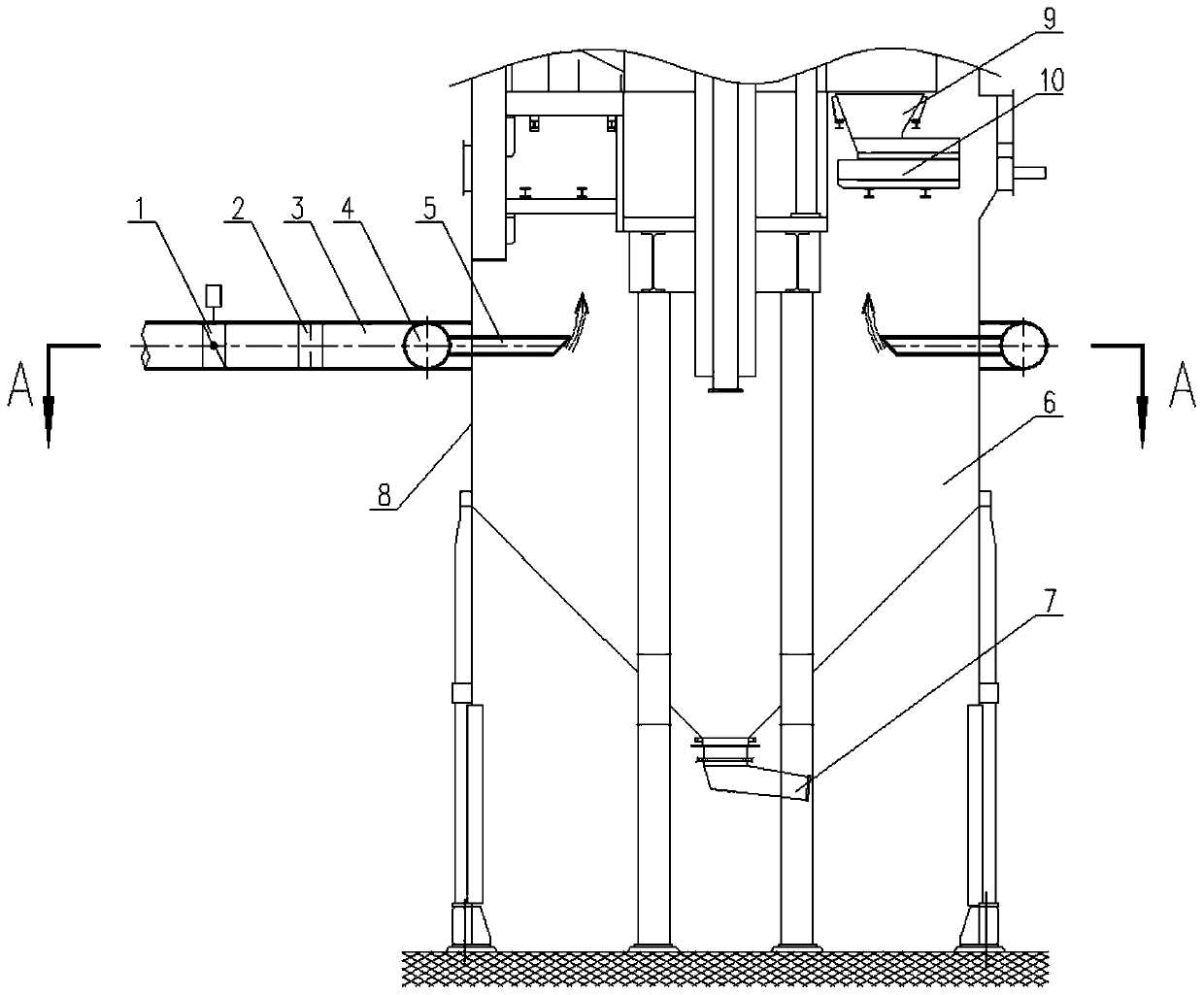
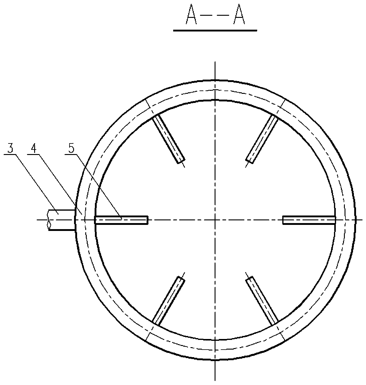
[0026] Such as Figure 1-2 As shown, the sleeve kiln lime cooling device in this embodiment includes a main pipe 3 , a ring pipe 4 and a branch pipe 5 , and the main pipe 3 is equipped with a regulating valve 1 and a flow meter 2 . The ring pipe 4 surrounds the kiln body 8 . A week along the ring pipe 4, several branch pipes 5 are evenly distributed, and the air outlets of the branch pipes 5 are located directly below the outlet of the lime funnel 9 on the top of the drawer type ash discharging device 10 . The branch pipe 5 is consistent with the number of the drawer type ash discharging device 10 and the uniform distribution angle of the horizontal section. The main pipe 3 and the ring pipe 4 are made of carbon steel, and the branch pipe 5 is made of carbon steel or stainless steel.
[0027] The lime cooling device of the sleeve kiln of this embodiment utilizes the negative pressure in the kiln body to draw normal-temperature air in the external environment into the cooling...
Embodiment 2
[0034] On the basis of the above embodiment, the annular pipe is a variable-diameter annular pipe, and the portion with the largest cross-sectional diameter and the portion with the smallest cross-sectional diameter of the variable-diameter annular pipe are arranged at both ends of the diameter of the annular pipe;
[0035] The cross-sectional diameter of the variable-diameter ring pipe changes uniformly from the smallest to the largest;
[0036] The air inlet is arranged at the part of the variable-diameter ring pipe with the largest cross-sectional diameter.
[0037] In this embodiment, the ring pipe is set as a ring pipe with variable cross-section, and the gas enters from the largest diameter, so that when the gas flows in the ring pipe, it will not cause each branch pipe to be damaged due to the different distances between the branch pipes and the intake pipe. The gas flow rate is different. Because the gas enters from the largest diameter, when a part of the air flows o...
Embodiment 3
[0039] On the basis of the above embodiments, the annular pipe is an equal-diameter annular pipe, and a plurality of air inlets are arranged on the outside of the equal-diameter annular pipe, and each of the air inlets is evenly arranged along the circumferential direction of the annular pipe. In this embodiment, a number of air inlets are evenly arranged on the outer side of the ring pipe, so that the flow rate of each air outlet can be guaranteed to be basically equal, and the gas segregation in the kiln body can be avoided.
[0040] Further, each of the air inlets communicates with a buffer container, and the volume of the buffer container is not less than 10 times the volume of the ring pipe. In this way, the air pressure of the buffered gas in the buffer container is approximately equal at each position, and the gas flow rate entering each air inlet is also approximately equal, thereby making the gas pressure in the ring pipe more uniform and the flow rate of each branch p...
PUM
 Abstract
Description
Claims
Application Information
 - R&D
- Intellectual Property
- Life Sciences
- Materials
- Tech Scout
- Unparalleled Data Quality
- Higher Quality Content
- 60% Fewer Hallucinations
Browse by: Latest US Patents, China's latest patents, Technical Efficacy Thesaurus, Application Domain, Technology Topic, Popular Technical Reports.
© 2025 PatSnap. All rights reserved.Legal|Privacy policy|Modern Slavery Act Transparency Statement|Sitemap|About US| Contact US: help@patsnap.com