Construction method for ultra-high-performance concrete corrugated steel web composite box girder bridge

A corrugated steel web, ultra-high-performance technology, applied in bridges, bridge materials, bridge construction, etc., can solve the problems of difficult concrete pouring, heavy bridge deck stress, and increased construction difficulty, and achieve on-site formwork and cast-in-place The effect of less construction work, good load distribution capacity and high bearing efficiency

Active Publication Date: 2017-05-10
HENAN PROVINCIAL COMM PLANNING & DESIGN INST CO LTD +1
View PDF7 Cites 6 Cited by
  • Summary
  • Abstract
  • Description
  • Claims
  • Application Information

AI Technical Summary

Problems solved by technology

Generally speaking, the maximum width of a single-box single-chamber cast-in-situ concrete box girder or a corrugated steel web composite box girder does not exceed 5m, and a wider single-box box girder must be formed by increasing the number of webs to form a single box with double rooms or a single box with multiple chamber section, or apply transverse prestressed steel beams to meet the requirements of bridge width and avoid excessive stress on the bridge deck, which will lead to problems such as increased beam weight, increased construction difficulty, and difficult pouring of concrete.

Method used


Image

  • Construction method for ultra-high-performance concrete corrugated steel web composite box girder bridge
  • Construction method for ultra-high-performance concrete corrugated steel web composite box girder bridge
  • Construction method for ultra-high-performance concrete corrugated steel web composite box girder bridge

Examples


Embodiment Construction

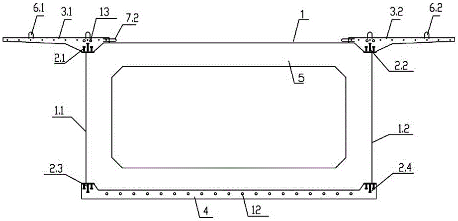
[0030] The construction method of the ultra-high performance concrete corrugated steel web composite box girder bridge of the present invention comprises the following steps:

[0031] The first step is to prefabricate the U-shaped groove structural parts of each span box girder according to the bridge design requirements: place the corrugated steel webs 1.1 and 1.2 on both sides in the prefabrication field, and weld studs on the upper and lower flanges Connectors 2.1, 2.2, 2.3, 2.4, then fix the pre-tensioned prestressed reinforcement 12 of the bottom plate of the box girder at a predetermined position on the tensioning platform, and stretch it to the design value, then bind the reinforcement mesh, and pre-embed the roof prestressed pipe 13, Erect formwork, pour ultra-high-performance concrete, and prefabricate U-shaped groove structural parts including bridge deck side plates 3.1, 3.2, box girder bottom plate 4, corrugated steel webs 1.1, 1.2, and transverse diaphragm 5, of wh...


PUM


Abstract

The invention discloses a construction method for an ultra-high-performance concrete corrugated steel web composite box girder bridge. The construction method comprises the steps that a U-shaped groove structural part of each span of box girder is prefabricated according to the design requirements at first; a bridge floor middle plate is prefabricated according to the prefabricated U-shaped groove structural part; a bridge abutment and a bridge pier are constructed, the prefabricated U-shaped groove structural part and the bridge floor middle plate are hoisted in position, transverse connecting steel bars are bound, and after transverse wet joints are poured, the complete box girder is formed; the next bridge pier is constructed, a second box girder is hoisted in position, corrugated steel webs of the adjacent box girders are welded, longitudinal connecting steel bars between the adjacent box girders are bound, longitudinal wet joints between the adjacent box girder segments are poured or a cross girder is casted in place, and a continuous bridge structure is formed; after wet joint concrete reaches the designed strength value, top plate prestressed steel strands are tensioned; and the above steps are repeated, so that the multi-span continuous bridge structure is completed. According to the construction method for the ultra-high-performance concrete corrugated steel web composite box girder bridge, the box girders are light in weight and small in torsional distortion, the bridge floor plate load distribution capacity is good, construction and erection are convenient, and the construction method has wide application prospects in large and middle span bridges.

Description

technical field [0001] The invention relates to highway and urban road bridge technology, in particular to a construction method of an ultra-high performance concrete corrugated steel web composite box girder bridge. Background technique [0002] The corrugated steel web is used to replace the concrete thick web of the traditional concrete box girder to form a corrugated steel web box girder. Not only the overall shape of the structure is beautiful, but also the problem of cracking of the traditional concrete box girder web is avoided, and the durability is good. Widely used in large and medium span bridges. [0003] Compared with the traditional concrete box girder, the width of the corrugated steel web box girder should not be too wide because the torsional stiffness and anti-distortion stiffness of the section of the corrugated steel web box girder are reduced. Generally speaking, the maximum width of a single-box single-chamber cast-in-situ concrete box girder or a corr...

Claims


Application Information

Patent Timeline
Patent Type & Authority Applications(China)
IPC IPC(8): E01D21/00E01D2/04E01D101/26
CPCE01D2/04E01D21/00E01D2101/26E01D2101/268
Inventor 杜战军李斐然张士红孙楠康健莫杰郭福利刘志献李海军张广敏刘晨
Owner HENAN PROVINCIAL COMM PLANNING & DESIGN INST CO LTD
Why Eureka
Try Eureka