High and low bin assembling integrated utility tunnel or draining canal

A comprehensive pipe gallery and integrated technology, applied in drainage structures, water conservancy projects, waterway systems, etc., can solve the problems of large cross-sectional size of prefabricated components, difficult waterproofing of seams, difficult construction quality control, etc., to achieve less wet work , Construction quality control is difficult, and the effect of reducing on-site labor and formwork consumption

Inactive Publication Date: 2017-05-10
DALIAN SANCHUAN BUILDING TECH CO LTD
View PDF5 Cites 4 Cited by
  • Summary
  • Abstract
  • Description
  • Claims
  • Application Information

AI Technical Summary

Problems solved by technology

All the work of pouring the integrated pipe gallery or drainage ditches of the upper and lower tanks on site is completed on site, with many wet operations, serious environmental pollution, long construction period, difficult vibration, difficult construction quality control, large labor demand, and high formwork cost; The full-section prefabricated integrated

Method used


Image

  • High and low bin assembling integrated utility tunnel or draining canal
  • High and low bin assembling integrated utility tunnel or draining canal
  • High and low bin assembling integrated utility tunnel or draining canal

Examples


Embodiment 1

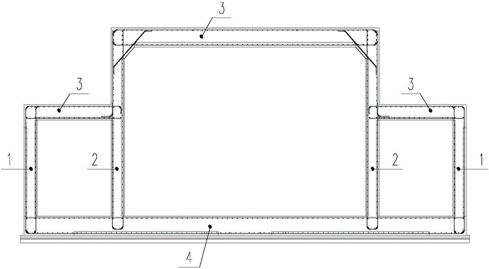
[0040] Such asfigure 1 An integrated integrated pipe gallery or drainage ditch for the upper and lower tanks shown, including the upper and lower tanks superimposed top plate, the superimposed bottom plate 4 or cast-in-place bottom plate, the superimposed outer wall panel 1 and the superimposed high and low tank transition wall panels 2. The laminated roof of the upper cabin and the lower cabin adopts the laminated roof 3 of the same structure. The laminated roof 3 includes the prefabricated roof layer and the cast-in-place layer of the roof. Including the cast-in-place layer of the bottom plate, the laminated exterior wall panel 1 includes the prefabricated layer of the exterior wall panel and the cast-in-place layer of the exterior wall panel, and the laminated upper and lower cabin transition wall panels 2 include the prefabricated layer of the transition wall panel and the cast-in-place layer of the transition wall panel; The bottom plate 4 or the cast-in-place bottom plate...

Embodiment 2

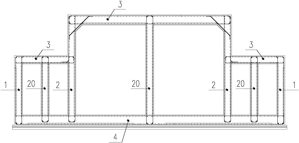
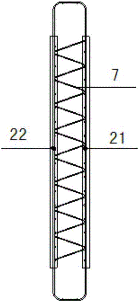
[0049] This embodiment is another form of high and low tank assembly integrated integrated pipe gallery or drainage ditch, see figure 2 , and the structure difference of embodiment 1 is that: in the lower cabin and the upper cabin, a laminated inner wall panel 20 is provided, and the laminated inner wall panel 20 includes the prefabricated layer of the inner wall panel and the cast-in-place layer of the inner wall panel, and the inner wall The slab prefabricated layer is composed of the inner prefabricated slab 21 of the inner wall panel, the outer prefabricated slab 22 of the inner wall panel and the truss reinforcement 7. The upper and lower chords of the truss reinforcement 7 are respectively embedded in the two-layer prefabricated slab and replace the vertical Steel bars, the vertical steel bars protruding from the lower ends of the inner and outer prefabricated slabs are bent and overlapped with each other, and the return bars formed by overlapping are anchored in the cas...


PUM


Abstract

The invention relates to the technical field of prefabricated concrete municipal structures, and provides a high and low bin assembling integrated utility tunnel or draining canal. The high and low bin assembling integrated utility tunnel or draining canal comprises high bin and low bin overlapping top plates, an overlapping bottom plate or cast-in-situ bottom plate, an overlapping outer wall plate and an overlapping high and low bin transition wall plate. The high bin and low bin overlapping top plates adopt overlapping top plates of the same structure. The overlapping top plates, the overlapping bottom plate, the overlapping outer wall plate and the overlapping high and low bin transition wall plate are each composed of a prefabricated part and a cast-in-situ part. The overlapping bottom plate or the cast-in-situ bottom plate is arranged on a basic pad layer or waterproof layer (or waterproof protective layer). Steel bars are arranged on the prefabricated parts of all the overlapping members. After the prefabricated parts are assembled on site, necessary stress and construction steel bars are added, and concrete is poured, so that the high and low bin assembling integrated utility tunnel or draining canal is formed. The high and low bin assembling integrated utility tunnel or draining canal can give the advantages of on-site casting and factory prefabrication into full play, reduce on-site wet operation, shorten the work period, improve construction quality, and guarantee the integrity, and is good in waterproof performance.

Description

technical field [0001] The invention relates to the technical field of prefabricated concrete municipal structures, in particular to an integrated integrated pipe gallery or drainage ditch assembled with high and low cabins. Background technique [0002] At present, there are mainly two methods for the construction of integrated pipe galleries or drainage ditches in China: one is the integrated pipe gallery or drainage ditches of the upper and lower cabins cast on site, and the other is the full-section prefabricated integrated pipe gallery or drainage ditches of the upper and lower cabins. All the work of pouring the integrated pipe gallery or drainage ditches of the upper and lower tanks on site is completed on site, with many wet operations, serious environmental pollution, long construction period, difficult vibration, difficult construction quality control, large labor demand, and high formwork cost; The full-section prefabricated integrated pipe gallery or drainage dit...

Claims


Application Information

Patent Timeline
IPC IPC(8): E02D29/00E03F5/00
CPCE02D29/10E03F5/00
Inventor 肖铁威孙伟丰梁伟孙辉高义民
Owner DALIAN SANCHUAN BUILDING TECH CO LTD
Why Eureka
Try Eureka