
Power generation system consisting of flexibly-connected clutch turbines

A power generation system and flexible connection technology, applied in wind power generation, hydropower generation, engines, etc., can solve the problems of high manufacturing difficulty, waste of wind resources, long construction period, etc., to improve energy conversion efficiency, high energy conversion efficiency, increase The effect of the ability to generate electricity

Active Publication Date: 2017-05-10
徐伟忠
View PDF7 Cites 1 Cited by
  • Summary
  • Abstract
  • Description
  • Claims
  • Application Information

AI Technical Summary

Problems solved by technology

In addition, using marine water resources to generate electricity, since the generator is installed in seawater, the sealing requirements for the generator and electrical equipment are extremely high, and the manufacturing is difficult, expensive, and installation is also very complicated
The disadvantage of using wind resources to generate electricity is that in the existing wind power generation, giant turbines and generators must be placed on towering large-diameter steel pipes or reinforced concrete pipes, which requires a huge amount of high-altitude suspension construction investment
Moreover, the density of generating units installed in the wind field is low, which wastes wind resources
Therefore, the existing hydroelectric power generation projects, ocean power generation projects, and wind power generation projects are all expensive and have a long construction period, and their impact on geology and the environment cannot be underestimated.

Method used


Image

  • Power generation system consisting of flexibly-connected clutch turbines
  • Power generation system consisting of flexibly-connected clutch turbines
  • Power generation system consisting of flexibly-connected clutch turbines

Examples


Embodiment Construction

[0011] The present invention will be further described in conjunction with the accompanying drawings.

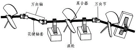
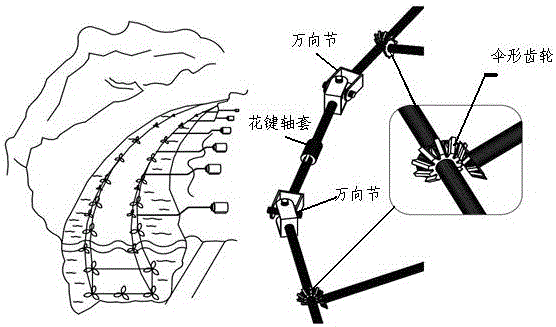
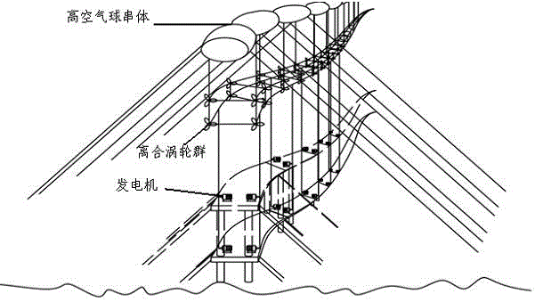
[0012] The power generation system of the present invention is composed of a plurality of clutch turbines connected in flexible series or flexible parallel to a turbine group or a subsystem composed of a turbine group connected to a generator through a flexible connecting rod string, wherein the clutch turbine is composed of a turbine body and a turbine The clutch is fixed between the shafts. The turbine body drives the turbine shaft to rotate forward through the clutch. The cardan shaft is composed of two universal joints and a pair of spline columns, sleeves or devices with the function of the cardan shaft. Multiple clutch turbines The turbine shaft flexibly connects the clutch turbines in series through the cardan shaft and the universal joint to form a turbine group, wherein the turbine shaft, the cardan shaft and the universal joint connected by the clutch turbine group ...


PUM


Abstract

A power generation system consisting of flexibly-connected clutch turbines relates to flexible connection and power generation technologies of turbines and is applicable to hydroelectric generation, ocean power generation, wind power generation and fluid kinetic energy or mechanical energy conversion. The power generation system is formed in the way that the plurality of clutch turbines are in series or parallel flexible connection to form a turbine set or a turbine group which is connected with a power generator through an output turning bar, the turbine set or the turbine group is arranged in river or sea in a submerging manner in the direction of water current or ocean current, or the clutch turbines are fixed on high-rising buildings or subjected to air floating and hauling suspension to utilize wind for power generation. As the plurality of clutch turbines are in flexible connection, the clutch turbines can be connected according to zigzagging of water current or ocean current geological environments; and the natural flow rate of water current or ocean current is fully utilized to impact and enable the clutch turbines to rotate, so that the power generator can generate power. The power generation system is low in construction cost, does not change the original ecology of the natural environment, and has the characteristics of high energy conversion efficiency, benefit and reliability and wide applicability.

Description

technical field [0001] The utility model relates to a power generation system formed by flexible connection of clutch turbines, relates to flexible connection of clutch turbines and turbine power generation technology, and is applicable to hydroelectric power generation, ocean power generation, wind power generation, and conversion of fluid kinetic energy and mechanical energy. Background technique [0002] Existing hydropower generation, in order to obtain a satisfactory hydropower effect, is often achieved by increasing the water level difference. Therefore, hydropower usually needs to block the river or build a dam to realize the water level difference on both sides of the dam body, and a A unit usually uses a single large-scale, heavy-weight giant turbine to drive the engine to generate electricity. Similarly, in the use of ocean water resources, a unit usually uses giant turbines to generate electricity, and wind resources also use giant turbines to generate electricity...

Claims


Application Information

Patent Timeline
Patent Type & Authority Applications(China)
IPC IPC(8): F03B13/00F03B11/00F03D9/25F03D80/00
CPCF03B11/00F03B13/00F03D9/008Y02B10/30Y02E10/20Y02E10/72
Inventor 徐伟忠
Owner 徐伟忠
Learn More