Power grid wire distributing equipment

A branching equipment and power grid technology, applied in mechanical equipment, gas/liquid distribution and storage, ship construction details, etc., can solve the problems of occupying vacuum equipment and stations, wasting vacuuming time, and low vacuuming efficiency , to achieve the effect of improving efficiency, reducing working hours and facilitating operation

Inactive Publication Date: 2017-05-10
DONGGUAN ZHIPEI ELECTROMECHANICAL TECH CO LTD
View PDF0 Cites 0 Cited by
  • Summary
  • Abstract
  • Description
  • Claims
  • Application Information

AI Technical Summary

Problems solved by technology

Although it can meet the basic needs of use, there are still some shortcomings. First, it will take a lot of man-hours to drill holes in the stainless steel pipe, and the use of this kind of pumping grid branching equipment has a limited flow area of ​​the masonry through the small holes. This leads to low vacuum efficiency, not only wasting a lot of vacuuming time, but also occupying vacuuming equipment and work stations for a long time

Method used


Image

  • Power grid wire distributing equipment

Examples


Embodiment Construction

[0018] The present invention is described in further detail now in conjunction with accompanying drawing. These drawings are all simplified schematic diagrams, which only illustrate the basic structure of the present invention in a schematic manner, so they only show the configurations related to the present invention.

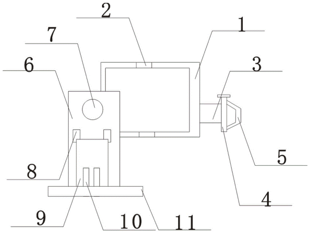
[0019] like figure 1 The preferred embodiment of the power grid branching equipment of the present invention shown includes a reducer 1, a buffer 2 is arranged in the reducer 1, the buffer 2 is fixed in the reducer 1, and a line distribution plate 3 is installed on one side of the reducer 1 , one end of the distribution board 3 is fixed on the reducer 1, the other end is provided with a pipe joint 5, the pipe joint 5 is fastened to the distribution board 3, and the first pump is installed between the pipe joint 5 and the distribution board 3 body, the other side of the reducer 1 is provided with a plug pump 6, the plug pump 6 is connected to the reducer 1, th...


PUM


Abstract

The invention discloses power grid wire distributing equipment, which comprises a speed reducer. A buffer is arranged in the speed reducer and is fixed into the speed reducer; a wire distributing plate is arranged on one side face of the speed reducer; one end of the wire distributing plate is fixed onto the speed reducer; a pipe connector is arranged on the other end of the wire distributing plate, and is fastened onto the wire distributing plate; a first pump body is arranged between the pipe connector and the wire distributing plate; a piston pump is arranged on the other side face of the speed reducer, is connected with the speed reducer, and is of a rectangular structure; a river water device is arranged in the piston pump and is fixed into the piston pump through a support frame; two cradle heads are further arranged in the piston pump; and a water pump is arranged at a position, close to the bottom part, between the two cradle heads. The power grid wire distributing equipment is compact in structure, convenient to operate, and favorable in air tightness, has a certain alleviated effect at the same time, and is prevented from influencing a vacuum pumping effect due to overhastiness.

Description

technical field [0001] The invention relates to a power grid branching device. Background technique [0002] After the double-layer low-temperature equipment filled with pearlite is installed, the interlayer needs to be vacuumized, and the fine pearlite particles should not escape into the vacuum equipment while vacuuming it. Existing pumping network branch line equipment is to drill a certain number of small holes on a stainless steel pipe with sufficient diameter, and then wrap the glass fiber cloth on the surface of the steel pipe. Although it can meet the basic needs of use, there are still some shortcomings. First, it will take a lot of man-hours to drill holes in the stainless steel pipe, and the use of this kind of pumping grid branching equipment has a limited flow area of ​​the masonry through the small holes. As a result, the vacuuming efficiency is low, not only wasting a lot of vacuuming time, but also occupying the vacuuming equipment and work stations for a lo...

Claims


Application Information

Patent Timeline
Patent Type & Authority Applications(China)
IPC IPC(8): F17C1/12
CPCF17C1/12F17C2203/0391
Inventor 戴晓海
Owner DONGGUAN ZHIPEI ELECTROMECHANICAL TECH CO LTD
Why Eureka
Try Eureka