Evaporator for ultrathin type air conditioner

An ultra-thin, evaporator technology, used in evaporators/condensers, heat sinks, tubular elements, etc., can solve problems such as layer height compression, reduced activity space, etc., to achieve stable cooling and heating, small overall thickness, light weight effect

Inactive Publication Date: 2017-05-10
SHENZHEN WOHAISEN TECH CO LTD
View PDF5 Cites 1 Cited by
  • Summary
  • Abstract
  • Description
  • Claims
  • Application Information

AI Technical Summary

Problems solved by technology

[0002] Under the current background technology, the thickness of the evaporator of the thin indoor unit of the central air conditioner is an important obstacle to limit the reduction of the overall volume. To accommodate components such as fans and evaporators, the corresponding volume is also relatively large. In existing high-rise buildings, the increase in the number of floors causes the floor height to be compressed. Because the thickness of the indoor unit determines the height of the ceiling within the same floor height, making The usable space on each floor due to the suspended ceiling is further compressed, resulting in a reduction in the space for people to move around

Method used


Image

  • Evaporator for ultrathin type air conditioner
  • Evaporator for ultrathin type air conditioner
  • Evaporator for ultrathin type air conditioner

Examples


Embodiment 1

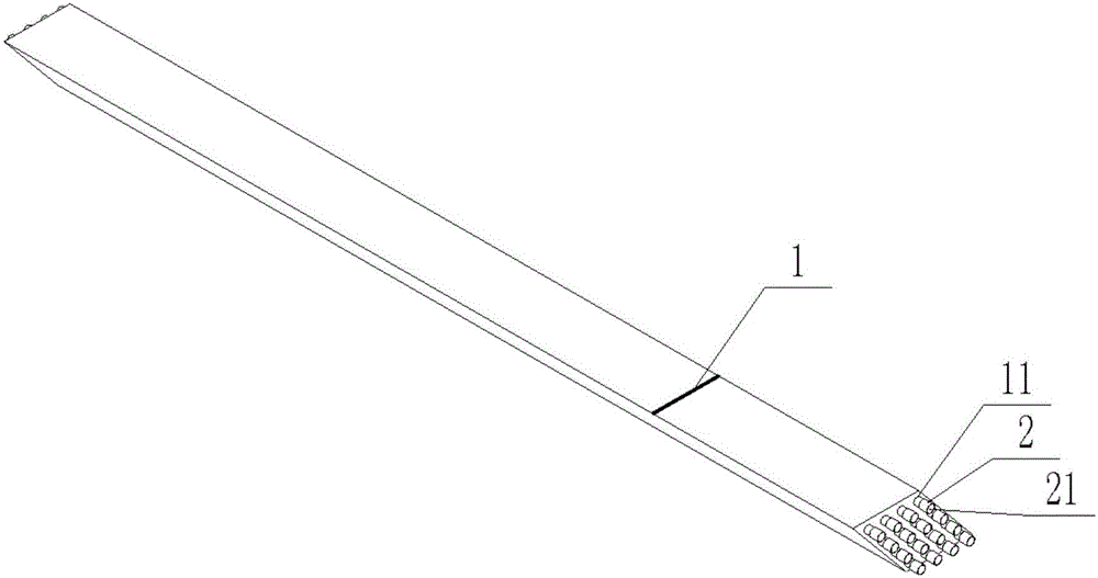
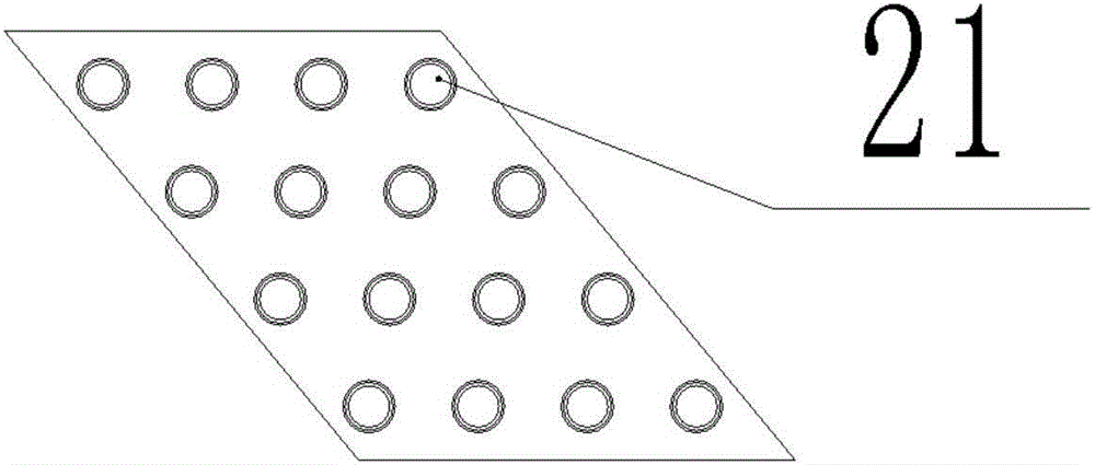
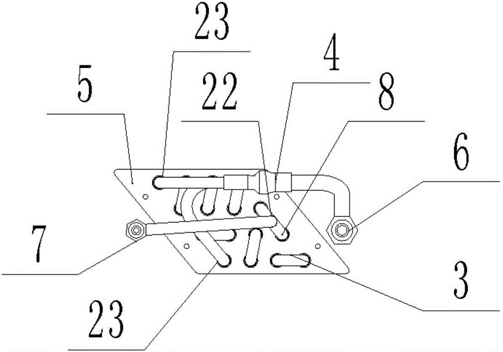
[0020] Please refer to the attached image 3 As shown, preferably, the pitch of the hypotenuse of the fin 1 is 50.800mm, the angle between the hypotenuse and the horizontal plane is 50.1°, and the height is 64.740mm, and the fin 1 is connected in series one by one, through The through holes 11 are arranged side by side in the body of the long U tube 2. The thickness of the fins 1 is 0.105 mm, the spacing between the fins 1 is 1.400 mm, and the total number is 607. The through holes 11 are 4 rows. There are 4 in each row. The said long U tubes 2 are in 4 rows, 2 in each row, and the nozzles 21 are connected by small elbows 3, small elbows 8 with openings or Y-shaped three-way pipes 4.

[0021] In this embodiment, the long U tubes 2 are preferably connected in the following order:

[0022] The first orifice 2101 in the first row and the first orifice 2113 in the fourth row are connected with the Y-shaped three-way pipe 4 to form an outlet pipe 23. The outlet pipe 24 is connected to t...

Embodiment 2

[0024] Figure 4 This is a schematic cross-sectional view of the fin set of Embodiment 2. Preferably, the difference from Embodiment 1 is that the pitch of the oblique side of the fin 1 of Embodiment 2 is 38.100mm, and the number of rows of through holes 11 is 3 rows. The described long U tube 2 has 3 rows, 2 in each row.

[0025] Since the specific connection method is not limited, preferably, one of the nozzles 21 is connected to the air outlet assembly 6 of the air conditioner, or no less than one, and the nozzles 21 belonging to the U pipe 2 of different length pass through the small elbow 8 with opening. It is connected to the air outlet assembly 6 of the air conditioner, one or more of the nozzles 21 are connected to the air inlet assembly 7 of the air conditioner, and the remaining nozzles 21 are connected by a small elbow 3.

Embodiment 3

[0027] Figure 5 It is a schematic cross-sectional view of the fin set of Embodiment 3. Preferably, the difference from Embodiments 1 and 2 is that the pitch of the hypotenuse of the fin 1 of Embodiment 2 is 25.400 mm, and the number of rows of through holes 11 is 2. The corresponding connection modes are not completely the same. The long U pipe 2 has two rows, with two in each row.

[0028] Since the specific connection method is not limited, preferably, one of the nozzles 21 is connected to the air outlet assembly 6 of the air conditioner, or no less than one, and the nozzles 21 belonging to the U-tube 2 of different length pass through the small elbow 8 with opening. It is connected to the air outlet assembly 6 of the air conditioner, one or more of the nozzles 21 are connected to the air inlet assembly 7 of the air conditioner, and the remaining nozzles 21 are connected with a small elbow 3.

[0029] The embodiment of the present invention is not limited to the above three exa...


PUM


Abstract

The invention relates to a component of air conditioning equipment, in particular to an evaporator for an ultrathin type air conditioner. The evaporator comprises a fin group, long U-shaped tubes and end plates; the fin group comprises fins and has a parallelogram section; the fins are arranged on tube bodies of the long U-shaped tubes side by side in such a manner that the fins are connected in series one by one; the long U-shaped tubes are arranged obliquely; tube openings of all the long U-shaped tubes are consistent in direction; and two ends of the fin group are connected with the end plates. The quadrangular section of the evaporator is changed into the parallelogram section, so that the overall thickness of the evaporator is compressed to the maximum extent, the heat exchange effect is good, uniform refrigeration and heating are realized, the size is small, and the weight is low.

Description

Technical field [0001] The present invention relates to air-conditioning equipment components, in particular to an evaporator for ultra-thin air conditioners. Background technique [0002] The thickness of the evaporator of the thin indoor unit of the central air conditioner under the current background art is an important obstacle to limit the reduction of the overall volume. In order to ensure the heat exchange efficiency, the existing evaporator is generally designed as a thicker type, causing the indoor unit to Accommodating components such as fans and evaporators, the corresponding volume is also too large. In the existing high-rise buildings, the increase in the number of floors causes the floor height to be compressed. Because the thickness of the indoor unit determines the ceiling height within the same floor height, The available space on each floor caused by the suspended ceiling is further compressed, resulting in reduced space for people's activities. [0003] Therefor...

Claims


Application Information

Patent Timeline
Patent Type & Authority Applications(China)
IPC IPC(8): F25B39/02F28F1/32
CPCF25B39/02F25B2339/02F28F1/325F28F2215/08
Inventor 王红胜
Owner SHENZHEN WOHAISEN TECH CO LTD
Why Eureka
Try Eureka